UPPER INSTRUMENT PANEL > REMOVAL |
| 1. PRECAUTION |
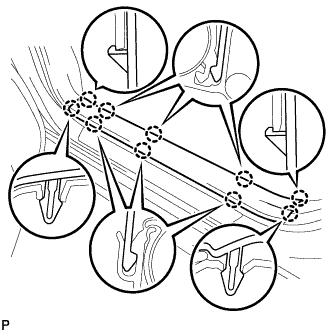
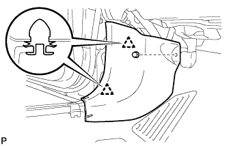
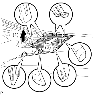
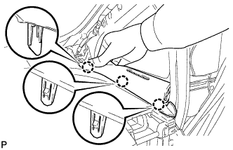
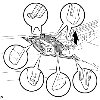
| 2. REMOVE REAR NO. 2 FLOOR BOARD |
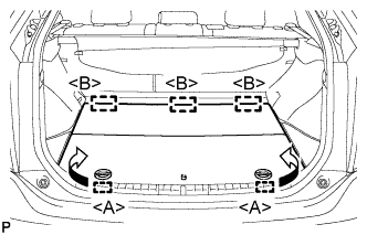 |
Disengage the 2 guides <A> as shown in the illustration.
Disengage the 3 guides <B> and remove the rear No. 2 floor board.
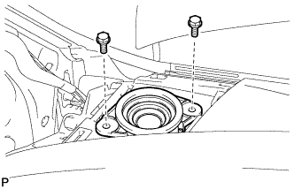
| 3. REMOVE REAR DECK FLOOR BOX |
Remove the rear deck floor box.
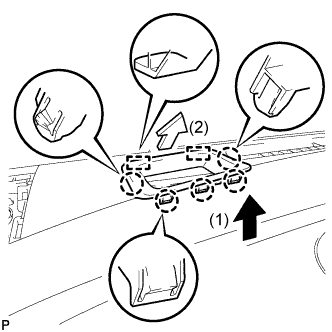
| 4. REMOVE REAR NO. 3 FLOOR BOARD |
 |
Disengage the 2 guides and remove the rear No. 3 floor board.
| 5. DISCONNECT CABLE FROM AUXILIARY BATTERY NEGATIVE TERMINAL |
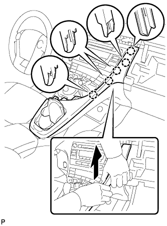
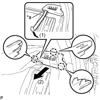
| 6. REMOVE INTEGRATION CONTROL AND PANEL ASSEMBLY |
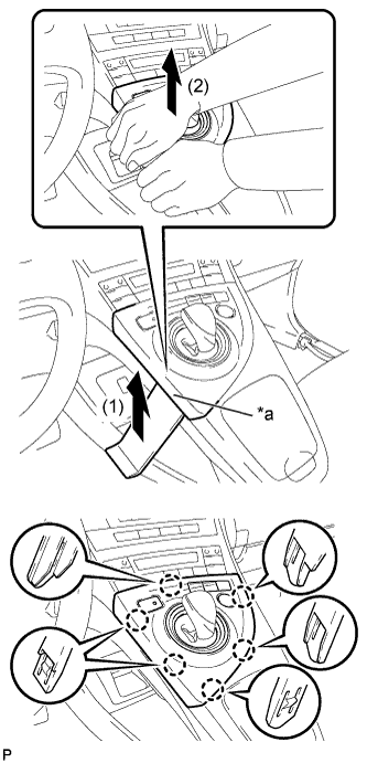 |
Using a moulding remover, slightly lift the panel at the position shown in the illustration.
| *a | Lift slightly |
Pull the integration control and panel assembly in the direction indicated by the arrow to disengage the 6 claws.
Disconnect each connector and remove the integration control and panel assembly.
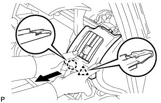
| 7. REMOVE LOWER CENTER INSTRUMENT CLUSTER FINISH PANEL SUB-ASSEMBLY |
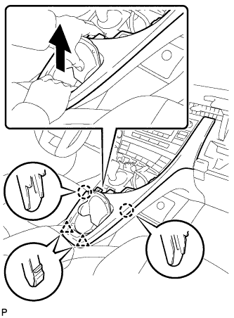 |
Pull the lower center instrument cluster finish panel sub-assembly in the direction indicated by the arrow to disengage the 2 claws and 2 clips.
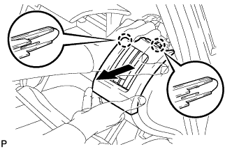
 |
Pull the lower center instrument cluster finish panel sub-assembly in the direction indicated by the arrow to disengage the 5 claws and remove the lower center instrument cluster finish panel sub-assembly.
| 8. REMOVE INSTRUMENT PANEL CUP HOLDER ASSEMBLY |
 |
Remove the 4 screws <C> and instrument panel cup holder assembly from the lower center instrument cluster finish panel sub-assembly.
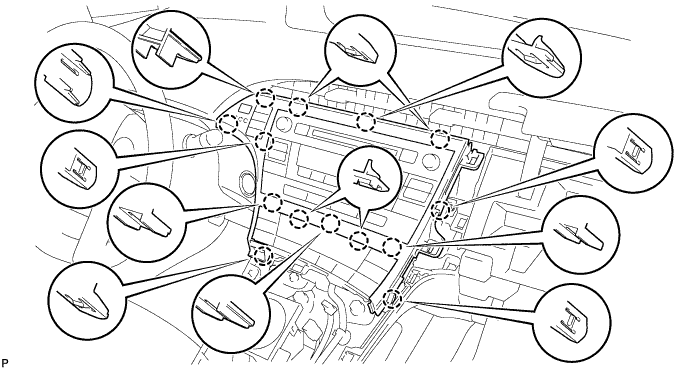
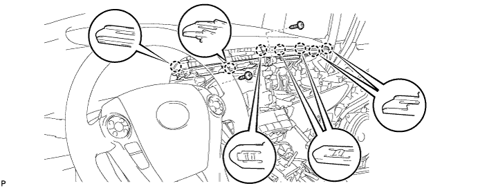
| 9. REMOVE INSTRUMENT CLUSTER FINISH PANEL GARNISH |
Disengage the 14 claws.
Disconnect the connector and remove the instrument cluster finish panel garnish.
| 10. REMOVE UPPER INSTRUMENT PANEL FINISH PANEL SUB-ASSEMBLY |
 |
Disengage the 3 claws.
Disconnect the connector and remove the upper instrument panel finish panel sub-assembly.
| 11. REMOVE CENTER INSTRUMENT CLUSTER FINISH PANEL SUB-ASSEMBLY (w/o Radio Receiver) |
 |
Disengage the 4 claws and remove the center instrument cluster finish panel sub-assembly.
| 12. REMOVE RADIO TUNER OPENING COVER WITH BRACKET (w/o Radio Receiver) |
 |
Remove the 4 bolts <B> and radio tuner opening cover with bracket.
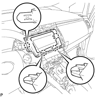
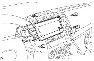
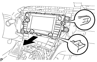
| 13. REMOVE RADIO AND DISPLAY RECEIVER ASSEMBLY WITH BRACKET (for Radio and Display Type) |
 |
Remove the 4 bolts.
 |
Disengage the 4 claws as shown in the illustration.
Disconnect each connector and remove the radio and display receiver assembly with bracket.
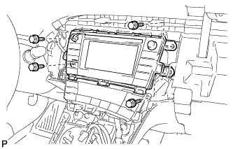
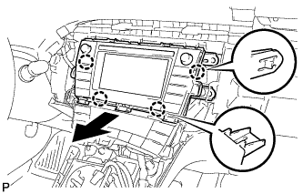
| 14. REMOVE NAVIGATION RECEIVER WITH BRACKET (for Navigation Receiver Type) |
 |
Remove the 4 bolts.
 |
Disengage the 4 claws and remove the navigation receiver with bracket as shown in the illustration.
Disconnect each connector.
| 15. REMOVE FRONT DOOR SCUFF PLATE LH |
 |
Disengage the 10 claws and remove the front door scuff plate LH.
| 16. REMOVE COWL SIDE TRIM SUB-ASSEMBLY LH |
 |
Remove the clip.
Disengage the 2 clips and remove the cowl side trim sub-assembly LH.
| 17. REMOVE LOWER INSTRUMENT PANEL FINISH PANEL ASSEMBLY |
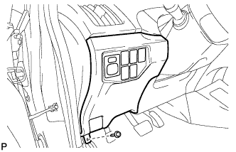 |
Remove the screw <C>.
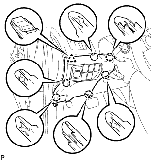 |
Disengage the 6 claws and clip as shown in the illustration.
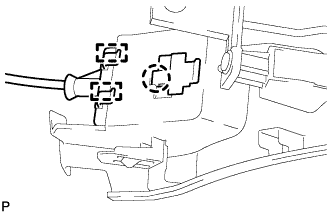 |
Disengage the claw and 2 guides and disconnect the hood lock control cable.
Disconnect each connector and clamp, and remove the lower instrument panel finish panel assembly.
| 18. REMOVE NO. 1 INSTRUMENT PANEL REGISTER |
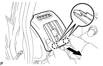 |
Pull the No. 1 instrument panel register in the direction indicated by the arrow to disengage the 2 claws.
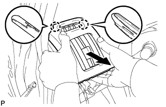 |
Pull the No. 1 instrument panel register in the direction indicated by the arrow to disengage the 2 claws and remove the No. 1 instrument panel register.
| 19. REMOVE NO. 1 CENTER INSTRUMENT CLUSTER FINISH PANEL |
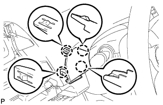 |
Disengage the 4 claws to remove the No. 1 center instrument cluster finish panel.
| 20. DISCONNECT FRONT DOOR OPENING TRIM WEATHERSTRIP LH |
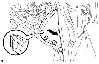
| 21. REMOVE INSTRUMENT PANEL FINISH PANEL END LH |
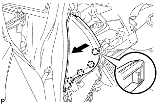 |
Pull the instrument panel finish panel end LH in the direction indicated by the arrow to disengage the 4 claws.
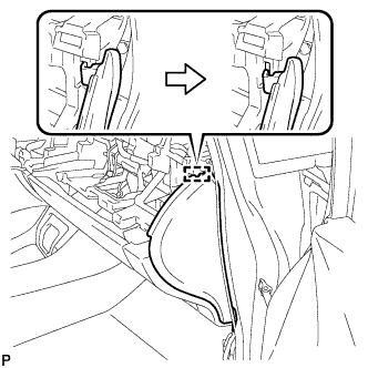
 |
Disengage the guide as shown in the illustration.
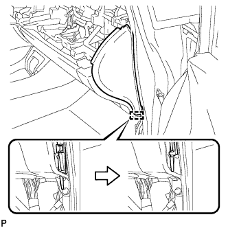
 |
Disengage the guide and remove the instrument panel finish panel end LH as shown in the illustration.
| 22. REMOVE NO. 1 SIDE DEFROSTER NOZZLE |
 |
Using a moulding remover, slightly lift the panel at the position shown in the illustration.
| *a | Lift slightly |
Pull the No. 1 side defroster nozzle in the direction indicated by the arrow to disengage the 3 claws and remove the No. 1 side defroster nozzle.
| 23. REMOVE NO. 2 INSTRUMENT PANEL REGISTER |
 |
Pull the No. 2 instrument panel register in the direction indicated by the arrow to disengage the claw and clip.
 |
Pull the No. 2 instrument panel register in the direction indicated by the arrow to disengage the 2 claws and remove the No. 2 instrument panel register.
| 24. REMOVE GLOVE COMPARTMENT DOOR |
Open the glove compartment door assembly.
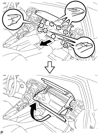 |
Pull the glove compartment door in the direction indicated by the arrow to disengage the 7 claws.
Pull the glove compartment door in the direction indicated by the arrow to remove the glove compartment door.
| 25. DISCONNECT FRONT DOOR OPENING TRIM WEATHERSTRIP RH |
| 26. REMOVE INSTRUMENT PANEL FINISH PANEL END RH |
 |
Pull the instrument panel finish panel end RH in the direction indicated by the arrow to disengage the 4 claws.
 |
Disengage the guide as shown in the illustration.
 |
w/o Airbag Cut Off Switch:
Disengage the guide and remove the instrument panel finish panel end RH as shown in the illustration.
w/ Airbag Cut Off Switch:
Disengage the guide.
Disconnect the connector and remove the instrument panel finish panel end RH as shown in the illustration.
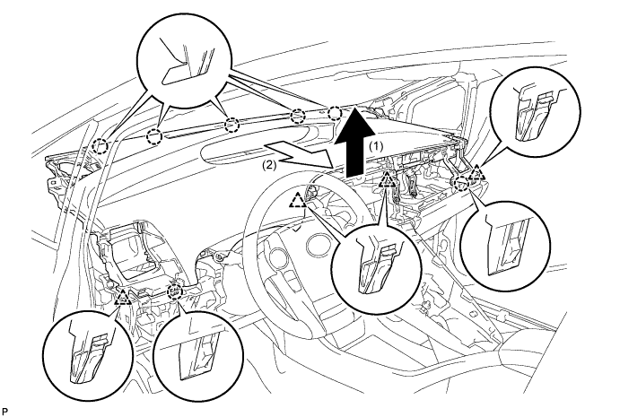
| 27. REMOVE FRONT PILLAR GARNISH LH |
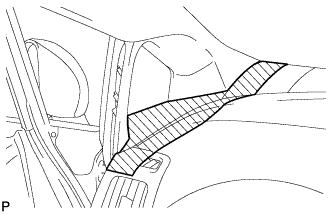 |
When removing the front pillar garnish LH, cover the shaded part in the illustration with a piece of cloth so that the interior parts will not be damaged.
 |
Pull the upper part of the garnish toward the inside of the cabin and disengage the 2 clips.
| *1 | Front Pillar Garnish Clip |
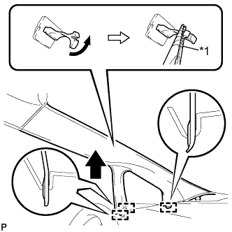 |
Turn the end of the front pillar garnish clip 90° with needle-nosed pliers and remove it from the front pillar garnish LH.
| *1 | Protective Tape |
Disengage the 3 guides.
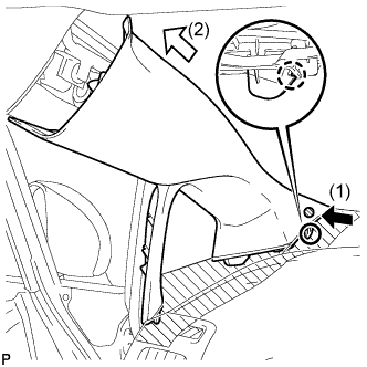 |
Disengage the claw while pressing the shaded part in the illustration in the direction indicated by the arrow (1).
Remove the front pillar garnish LH by pulling it in the direction indicated by the arrow (2) in the illustration.
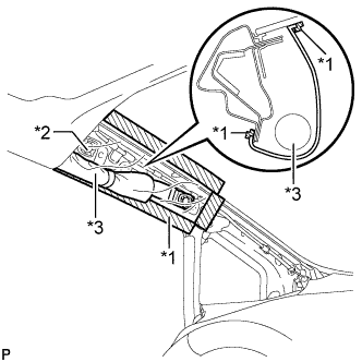 |
Protect the curtain shield airbag assembly.
| *1 | Adhesive Tape |
| *2 | Protective Cover |
| *3 | Curtain Shield Airbag Assembly |
Cover the airbag with a cloth or piece of nylon and secure the ends of the cover with tape as shown in the illustration.
| 28. REMOVE FRONT PILLAR GARNISH CORNER PIECE LH |
 |
Disengage the 3 claws and front pillar garnish corner piece LH as shown in the illustration.
| 29. REMOVE NO. 1 INSTRUMENT PANEL SPEAKER PANEL SUB-ASSEMBLY |
 |
Pull the No. 1 instrument panel speaker panel sub-assembly in the direction indicated by the arrow to disengage the 6 claws and 2 guides, and remove the No. 1 instrument panel speaker panel sub-assembly.
| 30. REMOVE FRONT NO. 2 SPEAKER ASSEMBLY |
 |
Remove the 2 bolts.
Disconnect the connector and remove the front No. 2 speaker assembly.
| 31. REMOVE FRONT PILLAR GARNISH RH |
| 32. REMOVE FRONT PILLAR GARNISH CORNER PIECE RH |
 |
Disengage the 3 claws and front pillar garnish corner piece RH as shown in the illustration.
| 33. REMOVE NO. 2 INSTRUMENT PANEL SPEAKER PANEL SUB-ASSEMBLY |
 |
Pull the No. 2 instrument panel speaker panel sub-assembly in the direction indicated by the arrow to disengage the 6 claws and 2 guides, and remove the No. 2 instrument panel speaker panel sub-assembly.
| 34. REMOVE FRONT NO. 2 SPEAKER ASSEMBLY |
| 35. REMOVE INSTRUMENT CLUSTER FINISH PANEL END |
 |
Pull the instrument cluster finish panel end in the direction indicated by the arrow to disengage the 5 claws and 2 guides, and remove the instrument cluster finish panel end.
| 36. REMOVE CENTER INSTRUMENT CLUSTER FINISH PANEL GARNISH |
Remove the 2 screws <C>.
Disengage the 7 claws.
Disconnect the connector and remove the center instrument cluster finish panel garnish.
| 37. DISCONNECT NO. 3 INSTRUMENT PANEL WIRE |
Check that the power switch is off.
Check that the cable is disconnected from the negative (-) battery terminal.
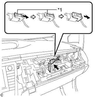 |
Slide the slider to release the lock, and then disconnect the connector.
| *1 | Slider |
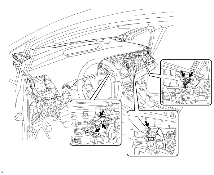
| 38. REMOVE UPPER INSTRUMENT PANEL ASSEMBLY |
Disconnect each connector.
Disengage the 2 clamps.
Remove the 2 bolts <B>.
Remove the 2 passenger airbag bolts <A>.
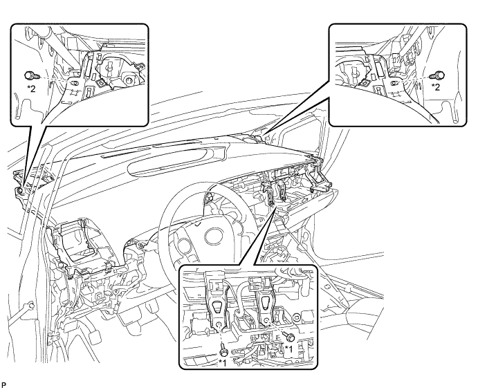
| *1 | Passenger Airbag Bolt <A> | *2 | Bolt <B> |
Pull the upper instrument panel assembly in the direction indicated by the arrow to disengage the 2 claws and 4 clips.
Pull the upper instrument panel assembly in the direction indicated by the arrow to disengage the 5 claws and remove the upper instrument panel assembly.