TCM > REMOVAL |
| 1. PRECAUTION (w/ Navigation System for HDD) |
| 2. REMOVE REAR NO. 2 FLOOR BOARD |
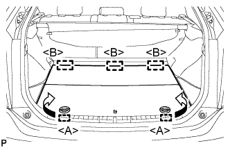 |
Disengage the 2 guides <A> as shown in the illustration.
Disengage the 3 guides <B> and remove the rear No. 2 floor board.
| 3. REMOVE REAR DECK FLOOR BOX |
Remove the rear deck floor box.
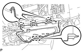
| 4. REMOVE REAR NO. 3 FLOOR BOARD |
 |
Disengage the 2 guides and remove the rear No. 3 floor board.
| 5. DISCONNECT CABLE FROM NEGATIVE BATTERY TERMINAL |
| 6. REMOVE NO. 2 INSTRUMENT PANEL UNDER COVER SUB-ASSEMBLY |
 |
Disengage the 3 claws and guide.
Disconnect each connector and remove the No. 2 instrument panel under cover sub-assembly.
| 7. REMOVE GLOVE COMPARTMENT DOOR ASSEMBLY |
for LHD:
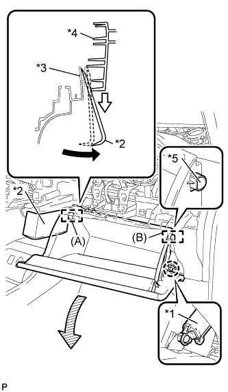 |
Disengage the claw and release the glove compartment door stopper.
| *1 | Glove Compartment Door Stopper Sub-assembly |
| *2 | Moulding Remover |
| *3 | Lower Instrument Panel Sub-assembly |
| *4 | Glove Compartment Door Assembly |
| *5 | Stopper |
Insert the moulding remover into the location shown in the illustration.
Move the moulding remover in the direction indicated by the arrow to bend the lower instrument panel sub-assembly and release the stopper (A).
for RHD:
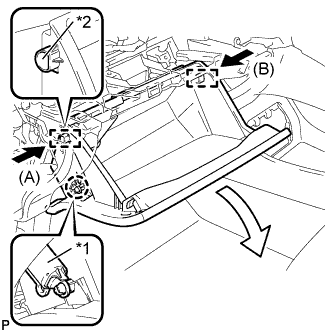 |
Disengage the claw and release the glove compartment door stopper.
| *1 | Glove Compartment Door Stopper Sub-assembly |
| *2 | Stopper |
Slightly bend stoppers (A) and (B) in the directions indicated by the arrows in the illustration and pull the glove compartment door assembly until the stoppers are released.
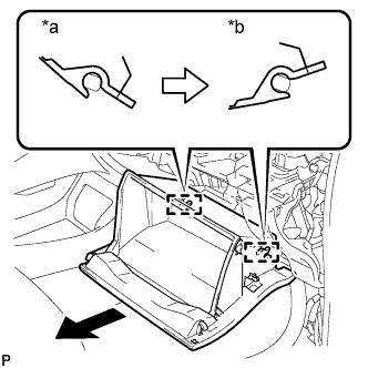 |
Open the glove compartment door assembly to approximately 55° from its closed position. Pull it horizontally in the direction indicated by the arrow to disengage the 2 hinges and remove the glove compartment door assembly.
| *a | Close |
| *b | Open Approximately |
| 8. REMOVE ECU INTEGRATION BOX (for LHD) |
Disconnect each connector.
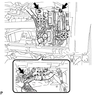 |
Disengage the 3 clamps and disconnect the wire harness.
Remove the bolt, 2 nuts and ECU integration box.
| 9. REMOVE ECU INTEGRATION BOX (for RHD) |
Disconnect each connector.
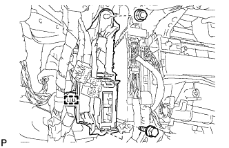 |
Disengage the clamp and disconnect the wire harness.
Remove the bolt, nut and ECU integration box.
| 10. REMOVE TRANSMISSION CONTROL ECU ASSEMBLY |
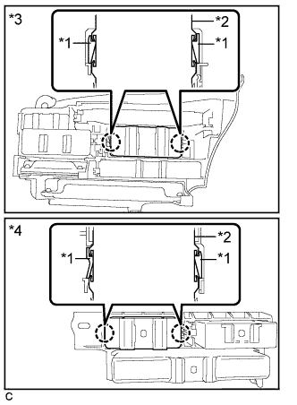 |
Disengage the 2 claws and remove the transmission control ECU assembly from the ECU integration box.
| *1 | Claw |
| *2 | Transmission Control ECU Assembly |
| *3 | LHD |
| *4 | RHD |
