INTELLIGENT PARKING ASSIST SYSTEM > "CHK" message(s) are displayed on the SIGNAL CHECK screen. |
| Item | Signal Input Method | Detail | DTC Output when Abnormal Result is Displayed | Signal Receiver |
| CAN | CAN communication | CAN communication condition | DTC is output | - |
| IPA SW | Vehicle wire harness | Parking assist pre support switch assembly signal input | DTC is not output | Parking assist pre support switch assembly |
| EPS | - | Brush information for EPS currently selected at individual setting screen | DTC is not output | - |
| HT SENS | Vehicle wire harness | Height control sensor signal input | DTC is output | Rear height control sensor sub-assembly RH |
| HT INIT | - | Height control sensor vehicle height difference setting status | DTC is output | - |
| HANDLE | CAN communication | CAN communication condition | DTC is output | - |
| DEST | CAN communication | CAN communication condition | DTC is output | - |
| 1.CHECK DISPLAY CHECK MODE |
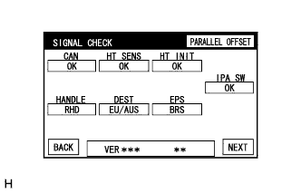 |
Check which items display "CHK" (red) on the SIGNAL CHECK screen.
| Result | Proceed to |
| "IPA SW" displays "CHK" (red). | A |
| "HT INIT" displays "CHK" (red). | B |
| Both "HT SENS" and "HT INIT" display "CHK" (red). | C |
| Any of "CAN", "HANDLE", and "DEST" displays "CHK" (red). | C |
| "EPS" displays "CHK" (red). | D |
|
| ||||
|
| ||||
|
| ||||
| A | |
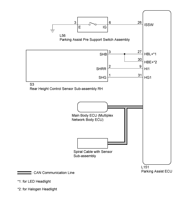
| 2.CHECK HARNESS AND CONNECTOR (PARKING ASSIST ECU - PARKING ASSIST PRE SUPPORT SWITCH ASSEMBLY) |
Disconnect the L151 connector from the parking assist ECU.
Disconnect the L56 connector from the parking assist pre support switch assembly.
Measure the resistance according to the value(s) in the table below.
| Tester Connection | Condition | Specified Condition |
| L151-26 (ISSW) - L56-6 (IG) | Always | Below 1 Ω |
|
| ||||
| OK | |
| 3.INSPECT PARKING ASSIST PRE SUPPORT SWITCH ASSEMBLY |
Remove the parking assist pre support switch assembly (Click here).
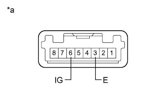 |
Measure the resistance according to the value(s) in the table below.
| Tester Connection | Condition | Specified Condition |
| 3 (E) - 6 (IG) | Parking assist pre support switch assembly pushed | Below 1 Ω |
| Parking assist pre support switch assembly not pushed | 10 kΩ or higher |
| *a | Component without harness connected (Parking Assist Pre Support Switch Assembly) |
|
| ||||
| OK | ||
| ||
