CENTER AIRBAG SENSOR ASSEMBLY > INSTALLATION |
| 1. INSTALL CENTER AIRBAG SENSOR ASSEMBLY |
Check that the power switch is off.
Check that the cable is disconnected from the negative (-) battery terminal.
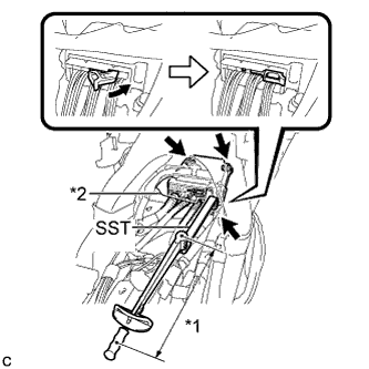 |
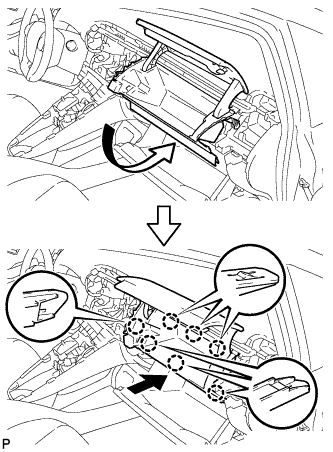
Using SST and a torque wrench, install the center airbag sensor assembly with the 3 bolts.
| *1 | Fulcrum Length |
| *2 | Waterproof Sheet |
Connect the connectors to the center airbag sensor assembly as shown in the illustration.
Check that the waterproof sheet is properly set.
Check that there is no looseness in the installation parts of the center airbag sensor assembly.
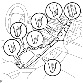
| 2. INSTALL UPPER INSTRUMENT PANEL FINISH PANEL ASSEMBLY |
Temporarily install the console box assembly.
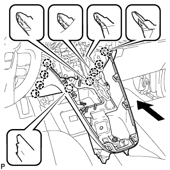 |
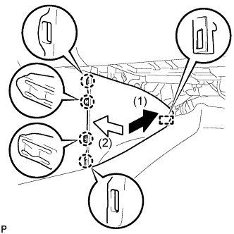
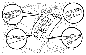
Engage the 9 claws as shown in the illustration.
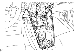 |
Install the to install the upper instrument panel finish panel assembly with the 2 bolts <A>.
Engage the clamp.
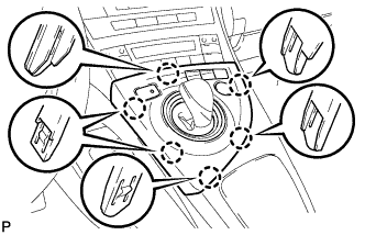
| 3. INSTALL CONSOLE BOX ASSEMBLY |
Connect each connector.
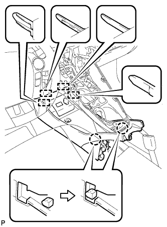 |
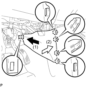
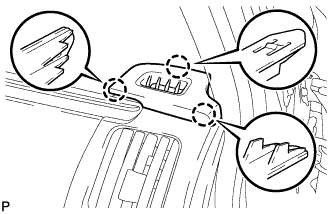
Engage the 4 guides and 2 claws as shown in the illustration.
Install the console box assembly with the bolt <B> and 2 clips.
| 4. INSTALL BOX BOTTOM MAT |
Engage the fastener to install the box bottom mat.
| 5. INSTALL FRONT NO. 2 CONSOLE BOX INSERT |
 |
Engage the guide and 4 claws to install the front No. 2 console box insert as shown in the illustration.
| 6. INSTALL FRONT NO. 1 CONSOLE BOX INSERT |
 |
Engage the guide and 4 claws to install the front No. 1 console box insert as shown in the illustration.
| 7. INSTALL NO. 2 CONSOLE BOX MOUNTING BRACKET |
Install the No. 2 console box mounting bracket with the 6 bolts <B>.
| 8. INSTALL ELECTRICAL KEY OSCILLATOR |
 |
Engage the clamp and install the electrical key oscillator.
Connect the connector.
| 9. INSTALL SHIFT LOCK CONTROL UNIT ASSEMBLY |
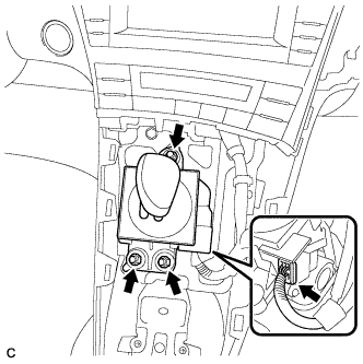 |
Install the shift lock control unit assembly with the 3 nuts.
Connect the connector to the shift lock control unit assembly.
| 10. INSTALL AIR CONDITIONING CONTROL ASSEMBLY |
Connect the connector.
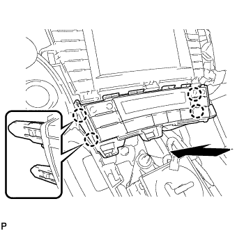 |
Engage the 4 claws to install the air conditioning control assembly.
| 11. INSTALL GLOVE COMPARTMENT DOOR |
Open the glove compartment door assembly.
 |
Insert the glove compartment door as shown in the illustration.
Engage the 7 claws to install the glove compartment door.
| 12. INSTALL NO. 2 INSTRUMENT PANEL REGISTER |
 |
Engage the 3 claws and clip to install the No. 2 instrument panel register.
| 13. INSTALL NO. 1 SIDE DEFROSTER NOZZLE |
 |
Engage the 3 claws to install the No. 1 side defroster nozzle.
| 14. INSTALL RADIO TUNER OPENING COVER WITH BRACKET (w/o Radio Receiver) |
 |
Install the radio tuner opening cover with bracket with the 4 bolts <B>.
| 15. INSTALL CENTER INSTRUMENT CLUSTER FINISH PANEL SUB-ASSEMBLY (w/o Radio Receiver) |
 |
Engage the 4 claws to install the center instrument cluster finish panel sub-assembly.
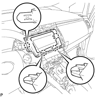
| 16. INSTALL RADIO AND DISPLAY RECEIVER ASSEMBLY WITH BRACKET (for Radio and Display Type) |
Connect each connector.
Engage the 4 claws.
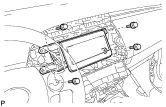
Install the radio and display receiver assembly with bracket with the 4 bolts.
| 17. INSTALL NAVIGATION RECEIVER WITH BRACKET (for Navigation Receiver Type) |
 |
Engage the 4 claws and temporarily install the navigation receiver with bracket as shown in the illustration.
Install the navigation receiver with bracket with the 4 bolts.
| 18. INSTALL UPPER INSTRUMENT PANEL FINISH PANEL SUB-ASSEMBLY |
 |
Connect the connector.
Engage the 3 claws to install the upper instrument panel finish panel sub-assembly.
| 19. INSTALL INSTRUMENT CLUSTER FINISH PANEL GARNISH |
Connect the connector.
Engage the 14 claws to install the instrument cluster finish panel garnish.
| 20. INSTALL LOWER CENTER INSTRUMENT CLUSTER FINISH PANEL SUB-ASSEMBLY |
 |
Engage the 7 claws and 2 clips to install the lower center instrument cluster finish panel sub-assembly.
| 21. INSTALL INTEGRATION CONTROL AND PANEL ASSEMBLY |
 |
Connect each connector.
Engage the 6 claws to install the integration control and panel assembly.
| 22. INSTALL REAR CONSOLE BOX ASSEMBLY |
| 23. CONNECT CABLE TO NEGATIVE BATTERY TERMINAL |
| 24. INSTALL REAR NO. 3 FLOOR BOARD |
 |
Engage the 2 guides to install the rear No. 3 floor board.
| 25. INSTALL REAR DECK FLOOR BOX |
Install the rear deck floor box.
| 26. INSTALL REAR NO. 2 FLOOR BOARD |
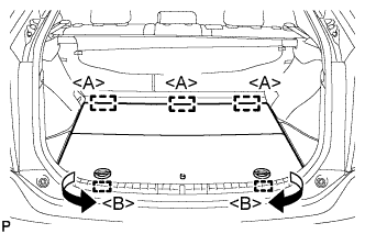 |
Engage the 3 guides <A>.
Engage the 2 guides <B> and install the rear No. 2 floor board as shown in the illustration.
| 27. PERFORM DIAGNOSTIC SYSTEM CHECK |
Perform a diagnostic system check (Click here).
| 28. INSPECT SRS WARNING LIGHT |
Inspect the SRS warning light (Click here).
