DTC P0069-273 Manifold Absolute Pressure - Barometric Pressure Correlation |
| DTC No. | INF Code | DTC Detection Condition | Trouble Area |
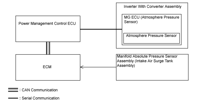
| P0069 | 273 | Difference between the atmospheric pressure value of the atmospheric pressure sensor in the inverter with converter assembly and the manifold absolute pressure sensor (for EGR control) exceeds a specified value. The same condition recurs within 3 hours when driving in EV mode. |
|
| 1.CHECK DTC OUTPUT (ENGINE CONTROL) |
Connect the intelligent tester to the DLC3.
Turn the power switch on (READY).
Fully depress the accelerator pedal for 5 seconds to start the engine and keep it running.
Enter the following menus: Powertrain / Engine and ECT / Trouble Codes.
Check if DTCs are output.
| Result | Proceed to |
| DTCs other than those listed in the following table are output. | A |
| Any of the following DTCs are also output. (w/ EGR system) | B |
| Any of the following DTCs are also output. (w/o EGR system) | C |
| DTC No. | Relevant Diagnosis |
| P0107 | Manifold Absolute Pressure/Barometric Pressure Circuit Low Input |
| P0108 | Manifold Absolute Pressure/Barometric Pressure Circuit High Input |
Turn the power switch off.
|
| ||||
|
| ||||
| A | |
| 2.CHECK DTC OUTPUT (HV) |
Connect the intelligent tester to the DLC3.
Turn the power switch on (IG).
Enter the following menus: Powertrain / Hybrid Control / Trouble Codes.
Check if DTCs are output.
| Result | Proceed to |
| P0069-273 only is output. | A |
| Any of the following DTCs are also output. | B |
| DTC No. | Relevant Diagnosis |
| P0A1A-151, 155, 156, 658, 659 | Generator Control Module |
| P0A1B-193, 512, 661, 786 | Drive Motor "A" Control Module |
| P0A1D-148 | Hybrid Powertrain Control Module |
| P2228-268 | Barometric Pressure Sensor "A" Circuit Low |
| P2229-269 | Barometric Pressure Sensor "A" Circuit High |
| P2511-149 | HV CPU Power Relay Sense Circuit Intermittent No Continuity |
| P324E-788 | MG-ECU Power Relay Intermittent Circuit |
| U0100-211, 530 | Lost Communication with ECM/PCM "A" |
| U0110 (all INF codes)*1 | Lost Communication with Drive Motor Control Module "A" |
Turn the power switch off.
|
| ||||
| A | |
| 3.READ VALUE USING INTELLIGENT TESTER (MAP, ATMOSPHERE PRESSURE) |
Connect the intelligent tester to the DLC3.
Turn the power switch on (IG).
Enter the following menus: Powertrain / Hybrid Control / Data List / MAP, Atmosphere Pressure.
Using the table, read the normal atmospheric pressure value for the applicable altitude.

Compare the MAP and Atmosphere Pressure values in the Data List with the normal atmospheric value from the table.
| Result | Proceed to |
| Other than the following. | A |
| Difference between MAP in Data List and normal atmospheric pressure value is 10 kPa or more. | B |
| Difference between Atmosphere Pressure in Data List and normal atmospheric pressure value is 10 kPa or more. | C |
Turn the power switch off.
|
| ||||
|
| ||||
| A | |
| 4.READ VALUE USING INTELLIGENT TESTER (MAP) |
Push the P position switch.
Enter the following menus: Powertrain / Hybrid Control / Data List / MAP
Read the MAP value in the Data List with the engine stopped.
While depressing the brake pedal, turn the power switch on (READY).
With the READY indicator light illuminated, fully depress the accelerator pedal.
Read the MAP value in the Data List with the engine running.
Compare the MAP value noted with the engine stopped and the MAP value noted with the engine running.
Turn the power switch off.
|
| ||||
| OK | ||
| ||
| 5.CHECK TERMINAL VOLTAGE (MANIFOLD ABSOLUTE PRESSURE SENSOR) |
 |
Disconnect the manifold absolute pressure sensor connector.
Turn the power switch on (IG).
Measure the voltage according to the value(s) in the table below.
| Tester Connection | Switch Condition | Specified Condition |
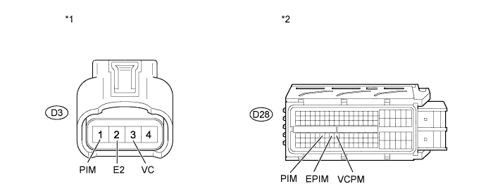
| D3-3 (VC) - D3-2 (E2) | Power switch on (IG) | 4.5 to 5.5 V |
| D3-1 (PIM) - D3-2 (E2) | Power switch on (IG) | 4.0 to 5.0 V |
| *1 | Front view of wire harness connector (to Manifold Absolute Pressure Sensor) |
Reconnect the manifold absolute pressure sensor connector.
| Result | Proceed to |
| Outside standard range | A |
| Within standard range | B |
|
| ||||
| A | |
| 6.CHECK HARNESS AND CONNECTOR (MANIFOLD ABSOLUTE PRESSURE SENSOR - ECM) |
Disconnect the manifold absolute pressure sensor connector.
Disconnect the ECM connector.
Measure the resistance according to the value(s) in the table below.
| Tester Connection | Condition | Specified Condition |
| D3-3 (VC) - D28-72 (VCPM) | Always | Below 1 Ω |
| D3-2 (E2) - D28-71 (EPIM) | ||
| D3-1 (PIM) - D28-69 (PIM) |
| Tester Connection | Condition | Specified Condition |
| D3-3 (VC) or D28-72 (VCPM) - Body ground | Always | 10 kΩ or higher |
| D3-2 (E2) or D28-71 (EPIM) - Body ground | ||
| D3-1 (PIM) or D28-69 (PIM) - Body ground |
| *1 | Front view of wire harness connector (to Manifold Absolute Pressure Sensor) | *2 | Front view of wire harness connector (to ECM) |
Reconnect the manifold absolute pressure sensor connector.
Reconnect the ECM connector.
|
| ||||
| OK | ||
| ||
| 7.REPLACE MANIFOLD ABSOLUTE PRESSURE SENSOR |
Replace the manifold absolute pressure sensor (Click here).
| NEXT | |
| 8.CHECK WHETHER DTC OUTPUT RECURS |
Connect the intelligent tester to the DLC3.
Turn the power switch on (IG).
Enter the following menus: Powertrain / Hybrid Control / Trouble Codes.
Check if DTCs are output.
| Result | Proceed to |
| DTC P0069-273 is not output. | A |
| DTC P0069-273 is output again. | B |
Turn the power switch off.
|
| ||||
| A | ||
| ||
