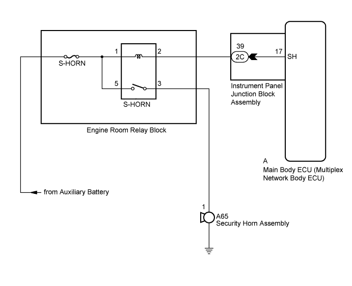
THEFT DETERRENT SYSTEM > Security Horn Circuit |
| 1.PERFORM ACTIVE TEST USING INTELLIGENT TESTER |
Connect the intelligent tester to the DLC3.
Turn the power switch on (IG).
Turn the intelligent tester on.
Select the item below in the Active Test and then check that the security horn assembly operates.
| Tester Display | Test Part | Control Range | Diagnostic Note |
| Security Horn | Security horn | ON/OFF | - |
|
| ||||
| OK | ||
| ||
| 2.INSPECT SECURITY HORN ASSEMBLY |
 |
Remove the security horn assembly (Click here).
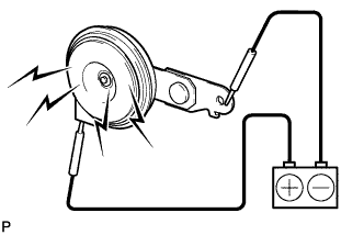
Check the operation of the security horn assembly.
| Battery Connection | Specified Condition |
| Battery positive (+) → A65-1 | Horn sounds |
| Battery negative (-) → Horn body |
|
| ||||
| OK | |
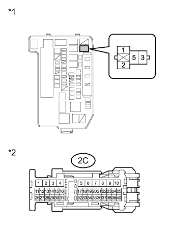
| 3.INSPECT INSTRUMENT PANEL JUNCTION BLOCK ASSEMBLY |
Disconnect the 2C instrument panel junction block assembly and A main body ECU (multiplex network body ECU) connectors.
Measure the resistance according to the value(s) in the table below.
| Tester Connection | Condition | Specified Condition |
| 2C-39 - A-17 (SH) | Always | Below 1 Ω |
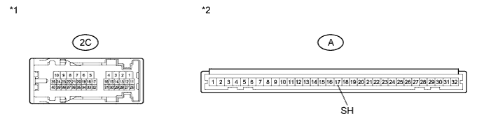
| *1 | Component without harness connected (Instrument Panel Junction Block Assembly) | *2 | Front view of wire harness connector (to Main Body ECU (Multiplex Network Body ECU)) |
|
| ||||
| OK | |
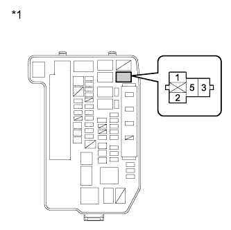
| 4.INSPECT S-HORN RELAY |
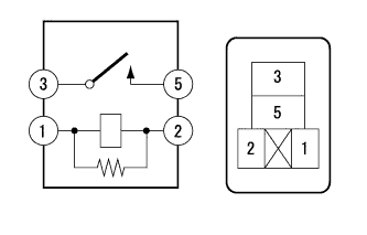 |
Remove the S-HORN relay from the engine room relay block.
Measure the resistance according to the value(s) in the table below.
| Tester Connection | Condition | Specified Condition |
| 3 - 5 | Battery voltage supplied between terminals 1 and 2 | Below 1 Ω |
| 3 - 5 | Battery voltage not supplied between terminals 1 and 2 | 10 kΩ or higher |
|
| ||||
| OK | |
| 5.CHECK HARNESS AND CONNECTOR (S-HORN RELAY POWER SOURCE) |
 |
Measure the voltage according to the value(s) in the table below.
| Tester Connection | Condition | Specified Condition |
| 1 - Body ground | Always | 11 to 14 V |
| 5 - Body ground | Always | 11 to 14 V |
| *1 | Front view of wire harness connector (to Engine Room Relay Block (S-HORN Relay)) |
|
| ||||
| OK | |
| 6.CHECK HARNESS AND CONNECTOR (S-HORN RELAY - INSTRUMENT PANEL JUNCTION BLOCK) |
 |
Measure the resistance according to the value(s) in the table below.
| Tester Connection | Condition | Specified Condition |
| 2 - 2C-39 | Always | Below 1 Ω |
| 2C-39 - Body ground | Always | 10 kΩ or higher |
| *1 | Front view of wire harness connector (to Engine Room Relay Block (S-HORN Relay)) |
| *2 | Front view of wire harness connector (to Instrument Panel Junction Block Assembly) |
|
| ||||
| OK | |
| 7.CHECK HARNESS AND CONNECTOR (SECURITY HORN ASSEMBLY - S-HORN RELAY) |
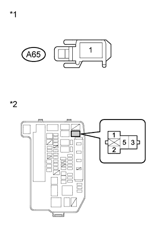 |
Disconnect the A65 security horn assembly connector.
Measure the resistance according to the value(s) in the table below.
| Tester Connection | Condition | Specified Condition |
| A65-1 - 3 | Always | Below 1 Ω |
| A65-1 - Body ground | Always | 10 kΩ or higher |
| *1 | Front view of wire harness connector (to Security Horn Assembly) |
| *2 | Front view of wire harness connector (to Engine Room Relay Block (S-HORN Relay)) |
|
| ||||
| OK | ||
| ||
