CONDENSER > INSTALLATION |
| 1. INSTALL COOLER CONDENSER ASSEMBLY |
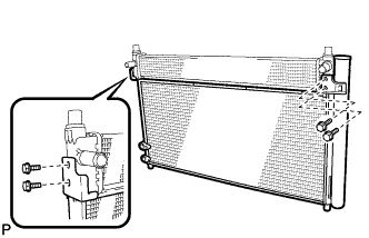 |
Install the cooler condenser assembly with the 4 bolts to the hybrid radiator assembly.
 |
Install the cooler condenser assembly.
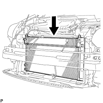
| 2. INSTALL NO. 2 FAN SHROUD |
 |
Install the No. 2 fan shroud with the 2 bolts.
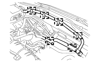 |
Connect the 6 water by-pass hose clamps to the No. 2 fan shroud.
 |
Connect the water by-pass hose to the radiator assembly.
 |
Connect the No. 1 water by-pass hose to the radiator assembly.
| 3. INSTALL HOOD LOCK SUPPORT SUB-ASSEMBLY |
 |
Install the upper radiator support with the 4 bolts.
Install the 2 cushions to the radiator support RH and radiator support LH.
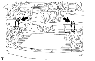 |
Install the radiator support RH and radiator support LH with the 2 bolts.
 |
Connect the 2 horn connectors.
 |
Connect the 2 wire harness clamps and connector to the fan shroud and cooling fan motor.
 |
Connect the connector to the No. 2 cooling fan motor.
 |
Connect the hood lock connector and hood lock control cable wire.
Connect the 3 wire harness clamps.
 |
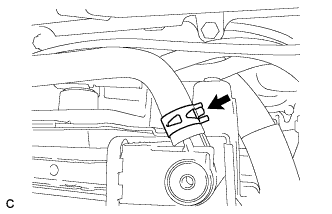
Connect the water by-pass hose clamp to the radiator support RH.
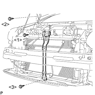
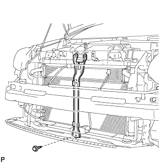
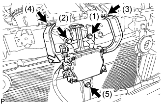
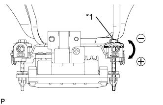
| 4. INSTALL NO. 1 INVERTER BRACKET |
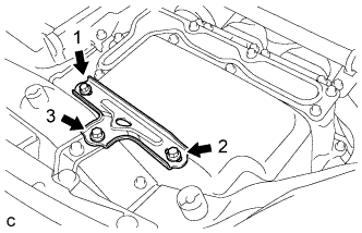 |
Temporarily install the No. 1 inverter bracket with the 3 bolts.
Tighten the 3 bolts in the order shown in the illustration.
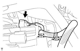
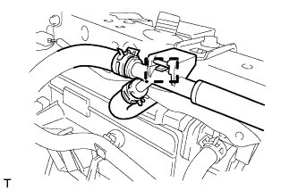
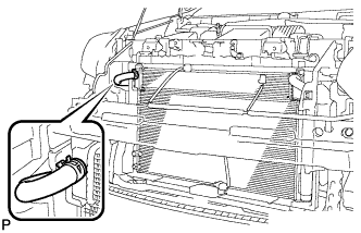
| 5. CONNECT NO. 7 INVERTER COOLING HOSE |
 |
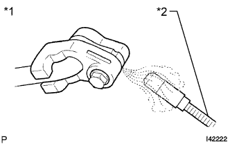
Using pliers, grip the claws of the clip and slide the clip to connect the No. 7 inverter cooling hose.
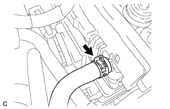
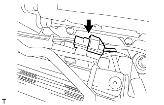
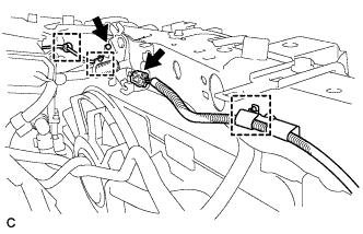
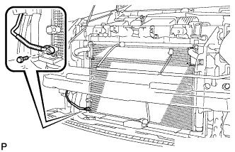
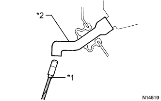
| 6. CONNECT NO. 5 INVERTER COOLING HOSE |
 |
Using pliers, grip the claws of the clip and slide the clip to connect the No. 5 inverter cooling hose.
| 7. CONNECT AIR CONDITIONING TUBE AND ACCESSORY ASSEMBLY |
Remove the attached vinyl tape from the pipe and the connecting part of the cooler condenser assembly.
Sufficiently apply compressor oil to a new O-ring and the fitting surface of the pipe joint.
Install the O-ring on the air conditioning tube and accessory assembly.
 |
Install the air conditioning tube and accessory assembly on the cooler condenser assembly with the bolt.
| 8. CONNECT DISCHARGE HOSE SUB-ASSEMBLY |
Remove the attached vinyl tape from the hose and the connecting part of the cooler condenser assembly.
Sufficiently apply compressor oil to a new O-ring and the fitting surface of the hose joint.
Install the O-ring on the discharge hose sub-assembly.
 |
Install the discharge hose sub-assembly on the cooler condenser assembly with the bolt.
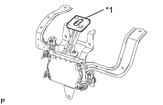
| 9. INSTALL MILLIMETER WAVE RADAR SENSOR BRACKET |
w/o Dynamic Radar Cruise Control System:
 |
Install the millimeter wave radar sensor bracket with the 3 bolts.
w/ Dynamic Radar Cruise Control System:
 |
Install the millimeter wave radar sensor bracket with the bolt.
| 10. INSTALL MILLIMETER WAVE RADAR SENSOR ASSEMBLY (w/ Dynamic Radar Cruise Control System) |
 |
Tighten the 5 bolts on the millimeter wave radar sensor assembly.
Connect the connector.
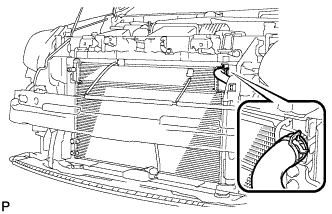
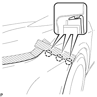
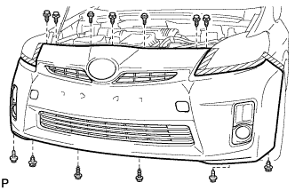
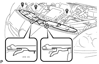
| 11. INSTALL FRONT BUMPER ASSEMBLY |
Connect the headlight cleaner hose. (w/ Headlight Cleaner System)
Connect each connector.
 |
Install the front bumper assembly as shown in the illustration.
 |
Engage the 3 claws to install the front bumper assembly.
 |
Engage the 2 guides and install the front spoiler cover. (w/ Front Spoiler)
Install the 2 clips and 2 screws. (w/ Front Spoiler)
 |
Install the 7 clips.
Install the 2 bolts and 4 screws.
 |
Install the screw.
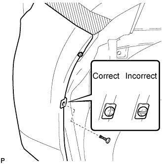 |
Install the pin hold clip.
| 12. ADD WINDSHIELD WASHER FLUID (w/ Headlight Cleaner System) |
Add washer fluid to the washer jar.
| 13. CONNECT CABLE TO NEGATIVE BATTERY TERMINAL |
| 14. INSTALL REAR NO. 3 FLOOR BOARD |
 |
Engage the 2 guides to install the rear No. 3 floor board.
| 15. INSTALL REAR DECK FLOOR BOX |
Install the rear deck floor box.
| 16. INSTALL REAR NO. 2 FLOOR BOARD |
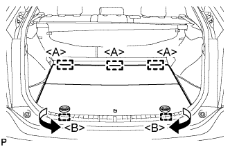 |
Engage the 3 guides <A>.
Engage the 2 guides <B> and install the rear No. 2 floor board as shown in the illustration.
| 17. CHARGE WITH REFRIGERANT |
Perform vacuum purging using a vacuum pump.
Charge with refrigerant HFC-134a (R134a).

| 18. ADD COOLANT (for Inverter) |
| DTC Code | Detection Item |
| P0A01-726 | Motor Electronics Coolant Temperature Sensor Circuit Range / Performance |
| P0A04-725 | Motor Electronics Coolant Temperature Sensor Circuit Intermittent |
| P0A08-264 | DC / DC Converter Status Circuit |
| P0A78-284 | Drive Motor "A" Inverter Performance |
| P0A78-286 | Drive Motor "A" Inverter Performance |
| P0A7A-322 | Generator Inverter Performance |
| P0A7A-324 | Generator Inverter Performance |
| P0A93-346 | Inverter Cooling System Performance |
| P0A94-553 | DC / DC Converter Performance |
| P0A94-557 | DC / DC Converter Performance |
| P0AEE-277 | Motor Inverter Temperature Sensor "A" Circuit Range / Performance |
| P0AF1-276 | Drive Motor Inverter Temperature Sensor "A" Circuit Intermittent / Erratic |
| P0BCD-315 | Generator Inverter Temperature Sensor Circuit Range / Performance |
| P0BD0-314 | Generator Inverter Temperature Sensor Circuit Intermittent / Erratic |
| P0C39-626 | DC / DC Converter Temperature Sensor "A" Range / Performance |
| P0C3C-625 | DC / DC Converter Temperature Sensor "A" Intermittent / Erratic |
| P0C3E-628 | DC / DC Converter Temperature Sensor "B" Range / Performance |
| P0C41-627 | DC / DC Converter Temperature Sensor "B" Intermittent / Erratic |
| P0C73-776 | Motor Electronics Coolant Pump "A" Control Performance |
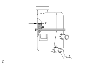 |
Slowly pour coolant into the reserve tank until it reaches the F line.
When using the intelligent tester:
Connect the intelligent tester to the DLC3.
Turn the power switch on (IG).
On the intelligent tester, enter the following menus: Powertrain / Hybrid Control / Active Test / Activate the Water Pump.
Keep the coolant at the F line in the reserve tank to compensate for the drop in coolant level when the air bleeds.
When not using the intelligent tester:
Turn the power switch on (READY). [*1]
Turn the power switch off and add coolant to the F line because the coolant level drops as the air bleeds. [*2]
Repeat steps [*1] and [*2] until air bleeding from the cooling system is completed.
After the air is completely bled from the cooling system, tighten the reserve tank cap.
|
Add coolant to the F line of the reserve tank.
| 19. WARM UP COMPRESSOR |
Keep the A/C switch on for at least 2 minutes to warm up the compressor.
| 20. INSPECT FOR REFRIGERANT LEAK |
After recharging with refrigerant, inspect for refrigerant leaks using a halogen leak detector.
Carry out the test under the following conditions:
 |
Using a halogen leak detector, inspect for refrigerant leaks from the refrigerant lines.
| *1 | Inspect for Leak |
| *2 | Halogen Leak Detector |
 |
Bring the halogen leak detector close to the drain hose with the detector's power off, and then turn the detector on.
| *1 | Halogen Leak Detector |
| *2 | Drain Hose |
If a refrigerant leak is not detected from the drain hose, remove the blower motor control from the cooling unit. Insert the halogen leak detector sensor into the unit and perform the test.
Disconnect the pressure switch connector and leave it for approximately 20 minutes. Bring the halogen leak detector close to the pressure switch and perform the test.
| 21. INSPECT FOR COOLANT LEAK (for Inverter) |
Remove the reserve tank cap.
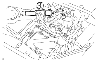 |
Install the radiator cap tester.
Pump the radiator cap tester to 122 kPa (1.2 kgf/ cm2, 17.7 psi), and then check that the pressure does not drop.
Reinstall the reserve tank cap.
| 22. ADJUST FOG LIGHT AIMING |
| 23. ADJUST HOOD SUB-ASSEMBLY |
| 24. ADJUST MILLIMETER WAVE RADAR SENSOR ASSEMBLY (w/ Dynamic Radar Cruise Control System) |
 |
| *1 | Approx. 10 m |
| *2 | Approx. 14 m |
Before adjusting the radar beam axis, prepare the vehicle as follows.
Check the tire pressure and adjust it if necessary.
Remove all excess weight from the vehicle (luggage, heavy objects, etc.).
 |
Check and adjust the vertical direction of the radar sensor.
| *1 | Level |
Remove dust, oil and foreign matter from the radar sensor's level rack.
Set a level on the radar sensor's level rack.
 |
Check that the level's air bubble is within the red frame.
| *1 | FR |
| *2 | LH |
| *3 | Level |
| *4 | Air Bubble |
| *5 | Bolt A |
| Adjustment Direction | Adjustment Procedure | Adjustment Angle |
| Vertical adjustment | Upward direction: Turn bolt A to negative (-) side | For every 1.4 rotations of adjustment bolt, sensor moves about 1° |
| Downward direction: Turn bolt A to positive (+) side |
 |
Adjust the reflector height.
| *1 | Millimeter Wave Radar Sensor |
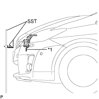
Adjust the reflector so that the center of SST reflector is the same height as the millimeter wave radar sensor.
 |
Place the reflector.
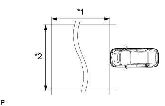
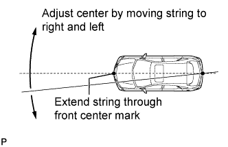
Hang the string (with weight) from the center of the vehicle's rear emblem. Mark the vehicle's rear center point on the ground. Repeat for the front of the vehicle.
 |
Set one end of the 10 m (32.8 ft.) string on the vehicle's rear center point. Run the string over the vehicle's front center point to a position 5 m (16.4 ft.) beyond the vehicle's front center point, as shown in the illustration. Mark the 5 m (16.4 ft.) position.
Using a tape measure, measure 15.7 mm (0.618 in.) to the right of the 5 m (16.4 ft.) position. Place the reflector at that position.
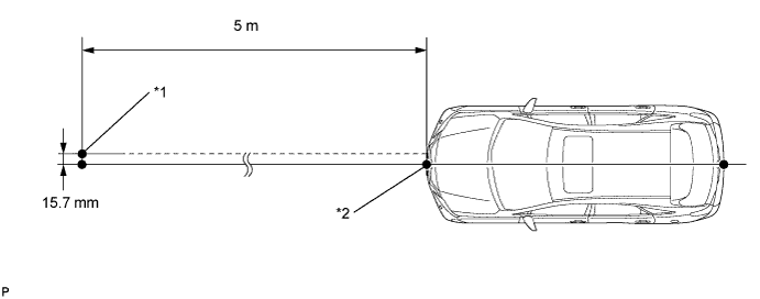
| *1 | Reflector Placement Point | *2 | Millimeter Wave Radar Sensor Position |
Check the radar beam axis.
When using the intelligent tester:
Connect the intelligent tester to the DLC3.
Turn the power switch on (IG).
Turn the intelligent tester on, and turn the cruise control main switch on.
Select "Auto" from the intelligent tester display screen.
Select "Radar Cruise" from the display screen.
Select "Utility" from the display screen.
Select "Beam Axis Adjustment" from the display screen.
Follow the tester display, and select "Next".
Check the following items on the laser cruise divergence data screen.
Check and adjust the horizontal direction of the radar sensor.
Check that the divergence of the radar beam axis is 0°.
 |
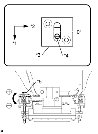
Based on the measured divergence of the beam axis, turn and adjust the bolt B for horizontal adjustment of the millimeter wave radar sensor using a screwdriver.
| *1 | Bolt B |
| Adjustment Direction | Adjustment Procedure | Adjustment Angle |
| Horizontal adjustment | Right direction: Turn bolt B to positive (+) side. | For every 2.5 rotations of adjustment bolt, sensor moves about 1° |
| Left direction: Turn bolt B to negative (-) side. |
Select "Next". The driving learning value is automatically reset.
Disconnect the intelligent tester from the DLC3.
Recheck and readjust the vertical direction of the radar sensor.
|
Set a level on the radar sensor's level rack.
| *1 | Level |
|
Check that the level's air bubble is within the red frame.
| *1 | FR |
| *2 | LH |
| *3 | Level |
| *4 | Air Bubble |
| *5 | Bolt A |
| Adjustment Direction | Adjustment Procedure | Adjustment Angle |
| Vertical adjustment | Upward direction: Turn bolt A to negative (-) side | For every 1.4 rotations of adjustment bolt, sensor moves about 1° |
| Downward direction: Turn bolt A to positive (+) side |
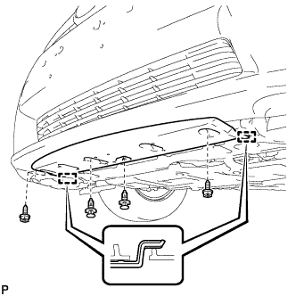
| 25. INSTALL RADIATOR SUPPORT OPENING COVER |
 |
Engage the 2 claws and install the radiator support opening cover.
Install the 3 clips.
