CYLINDER HEAD > REASSEMBLY |
| 1. INSTALL SPARK PLUG TUBE |
 |
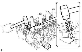
Apply adhesive onto the shaded area of a new spark plug tube.
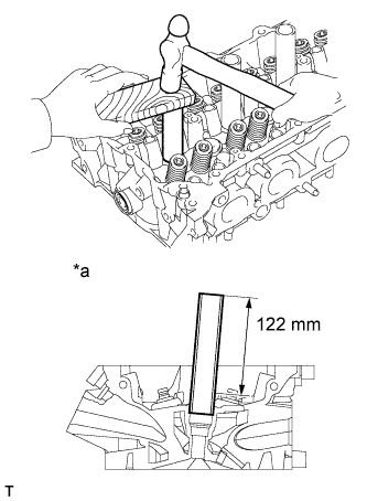 |
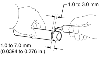
Using a wooden block and hammer, tap in the spark plug tube to the specified protrusion height.
| *a | Cylinder Head Casting Surface: |
| 2. INSTALL STUD BOLT |
Using an E8 "TORX" socket, install the stud bolts.
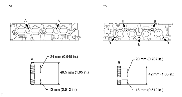
| *a | Intake Side: | *b | Exhaust Side: |
| 3. INSTALL NO. 2 STRAIGHT SCREW PLUG |
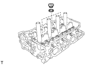 |
Using a 10 mm straight hexagon wrench, install 3 new gaskets and the 3 straight screw plugs.
| 4. INSTALL VALVE SPRING SEAT |
Install the valve spring seats to the cylinder head.
| 5. INSTALL VALVE STEM OIL SEAL |
 |
Apply a light coat of engine oil to a new oil seal.
| *a | Intake Side: |
| *b | Exhaust Side: |
| *c | Gray |
| *d | Black |
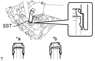 |
Using SST, push on the oil seal.
| *a | CORRECT |
| *b | INCORRECT |
| 6. INSTALL INTAKE VALVE |
Place the cylinder head on wooden blocks.
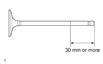 |
Apply engine oil to each valve over an area 30 mm (1.18 in.) or more from its tip, as shown in the illustration.
Install the valve, compression spring and spring retainer to the cylinder head.
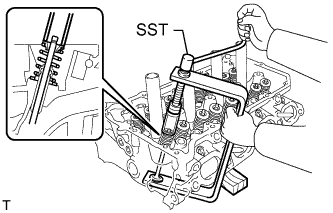 |
Using SST, compression spring and install the valve retainer locks.
 |
Using a plastic-faced hammer, lightly tap the valve stem tip to ensure a proper fit.
| 7. INSTALL EXHAUST VALVE |
Place the cylinder head on wooden blocks.
 |
Apply engine oil to each valve over an area 30 mm (1.18 in.) or more from its tip, as shown in the illustration.
Install the valve, compression spring and spring retainer to the cylinder head.
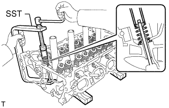 |
Using SST, compression spring and install the valve retainer locks.
 |
Using a plastic-faced hammer, lightly tap the valve stem tip to ensure a proper fit.
