ENGINE UNIT > REASSEMBLY |
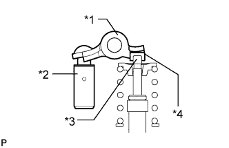
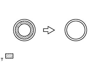
| 1. INSTALL STIFFENING CRANKCASE RING PIN |
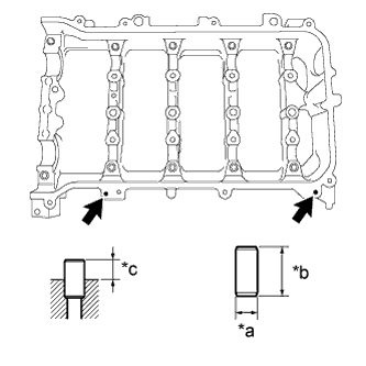
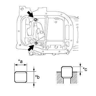 |
| *a | Width |
| *b | Height |
| *c | Protrusion Height |
Using a plastic-faced hammer, tap in 2 new ring pins until they stop.
| Item | Protrusion Height | Height | Width |
| Ring pin | 3.0 mm (0.118 in.) | 11 mm (0.433 in.) | 8 mm (0.315 in.) |
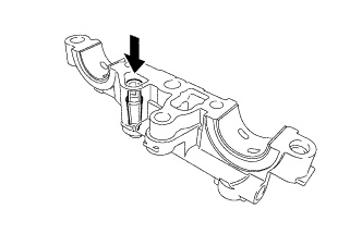
| 2. INSTALL STIFFENING CRANKCASE STUD BOLT |
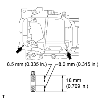 |
Using an E6 "TORX" socket wrench, install the stud bolts as shown in the illustration.
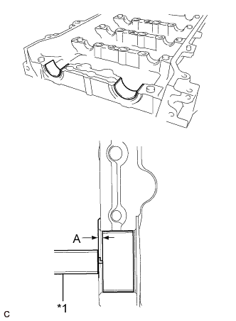
| 3. INSTALL STIFFENING CRANKCASE ASSEMBLY |
 |
Apply seal packing in a continuous line as shown in the illustration.
| Area | Specified Condition |
| Continuous Line | 2.0 to 3.0 mm (0.0787 to 0.118 in.) |
| A | 4.5 to 5.5 mm (0.177 to 0.217 in.) |
 |
Install the stiffening crankcase with the 11 bolts in the sequence shown in the illustration.
| Item | Specified Condition |
| Bolt A | 138 mm (5.43 in.) |
| Bolt B | 35 mm (1.38 in.) |
| Bolt C | 70 mm (2.76 in.) |
Recheck the torque for bolts 1 and 2.
Wipe off any excess seal packing with a clean piece of cloth.
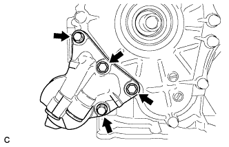
| 4. INSTALL OIL PUMP ASSEMBLY |
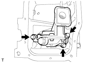 |
Install the oil pump with the 3 bolts.
| 5. INSTALL NO. 2 OIL PAN SUB-ASSEMBLY |
Remove any old packing material and be careful not to drop any oil on the contact surfaces of the cylinder block and oil pan.
 |
Apply a continuous bead of seal packing (Diameter 4.0 mm (0.157 in.)) as shown in the illustration.
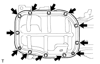 |
Install the No. 2 oil pan with the 10 bolts and 2 nuts.
| 6. INSTALL OIL PAN DRAIN PLUG |
 |
Install a new gasket and the drain plug.
| 7. INSTALL ENGINE REAR OIL SEAL |
Apply MP grease to the lip of a new oil seal.
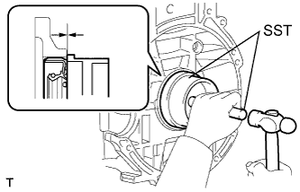 |
Using SST and a hammer, tap in the oil seal until its surface is flush with the rear oil seal retainer edge.
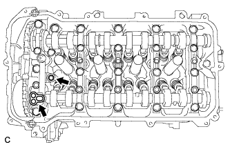
| 8. INSTALL CYLINDER BLOCK WATER DRAIN COCK SUB-ASSEMBLY |
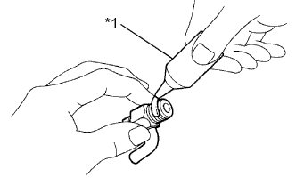 |
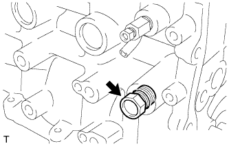
Apply adhesive to the threads of the cylinder block water drain cock.
| *1 | Adhesive |
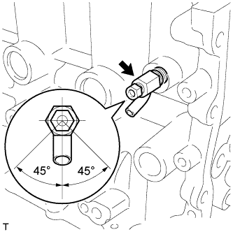 |
Install the drain cock as shown in the illustration.
Install the drain cock plug to the drain cock.
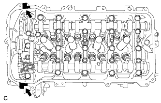
| 9. INSTALL NO. 1 TAPER SCREW PLUG |
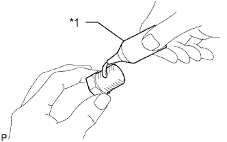 |
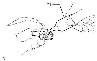
Apply adhesive to 2 or 3 threads of the taper screw plug.
| *1 | Adhesive |
 |
Install the taper screw plug.
| 10. INSTALL VENTILATION VALVE SUB-ASSEMBLY |
 |
Apply adhesive to the threads of the ventilation valve sub-assembly.
| *1 | Adhesive |
 |
Install the ventilation valve sub-assembly.
| 11. INSTALL CYLINDER HEAD GASKET |
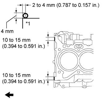 |
Apply seal packing (Diameter 4.0 mm (0.157 in.)) to the cylinder block as shown in the illustration.
| *1 | Cylinder Block |
 | Engine Front |
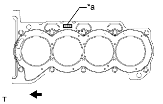 |
Place a new cylinder head gasket on the cylinder block with the Lot No. stamp facing upward.
| *a | Lot No. |
| Engine Front |
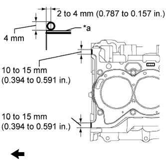 |
Apply seal packing (Diameter 4.0 mm (0.157 in.)) to the new cylinder head gasket as shown in the illustration.
| *1 | Cylinder Head Gasket |
| Engine Front |
 |
After tightening the cylinder head bolts, wipe off the seal packing material seeped out from the contact surfaces between the cylinder head and cylinder block.
| *a | Before wiping off: |
| *b | After wiping off: |
| 12. INSTALL CYLINDER HEAD SUB-ASSEMBLY |
Place the cylinder head on the cylinder block.
Install the plate washers to the cylinder head bolts.
Apply a light coat of engine oil to the threads and under the heads of the cylinder head bolts.
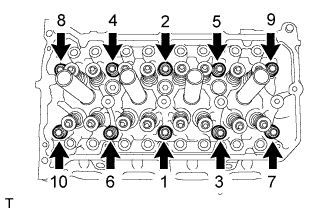 |
Step 1:
Using a 10 mm bi-hexagon wrench, install and uniformly tighten the 10 cylinder head bolts in several steps, in the sequence shown in the illustration.
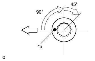 |
Step 2:
| *a | Paint Mark |
 | Engine Front |
Mark each cylinder head bolt head with paint as shown in the illustration.
Tighten the cylinder head bolts 90° in the sequence shown in step 1.
Step 3:
Tighten the cylinder head bolts another 45° in the sequence shown in step 1.
Check that the paint mark is now at a 135° angle to the front.
| 13. INSTALL VALVE STEM CAP |
Apply a light coat of engine oil to the valve stem ends.
Install the 16 valve stem caps to the cylinder head.
| 14. INSTALL VALVE LASH ADJUSTER ASSEMBLY |
Inspect each valve lash adjuster before installing it (Click here).
Install the 16 valve lash adjusters to the cylinder head.
| 15. INSTALL NO. 1 VALVE ROCKER ARM SUB-ASSEMBLY |
 |
Apply engine oil to the valve lash adjuster tips and valve stem cap ends.
| *1 | Valve Rocker Arm |
| *2 | Valve Lash Adjuster |
| *3 | Valve Stem |
| *4 | Valve Stem Cap |
Make sure that the No. 1 valve rocker arms are installed as shown in the illustration.
| 16. INSTALL CAMSHAFT HOUSING STRAIGHT PIN |
 |
| *a | Width |
| *b | Height |
| *c | Protrusion Height |
Using a plastic-faced hammer, tap in a new straight pin to the specified protrusion height.
| Item | Protrusion Height | Height | Width |
| Straight pin | 6.5 to 7.5 mm (0.256 to 0.295 in.) | 14 mm (0.551 in.) | 6.0 mm (0.236 in.) |
| 17. INSTALL NO. 1 CAMSHAFT BEARING |
Clean both surfaces of the bearings.
Install the 2 No. 1 camshaft bearings.
 |
Using a vernier caliper, measure the distance between the bearing cap edge and the camshaft bearing edge.
| *1 | Vernier Caliper |
| 18. INSTALL OIL CONTROL VALVE FILTER |
 |
Check that no foreign matter is on the mesh part of the oil control valve filter.
Install the oil control valve filter.
| 19. INSTALL NO. 2 CAMSHAFT BEARING |
Clean both surfaces of the bearings.
Install the 2 No. 2 camshaft bearings.
 |
Using a vernier caliper, measure the distance between the bearing cap edge and the camshaft bearing edge.
| *1 | Vernier Caliper |
| 20. INSTALL NO. 2 CAMSHAFT |
Clean the camshaft journals.
Apply a light coat of engine oil to the camshaft journals, camshaft housings and bearing caps.
 |
Install the No. 2 camshaft to the camshaft housing.
| 21. INSTALL CAMSHAFT |
Clean the camshaft journals.
Apply a light coat of engine oil to the camshaft journals, camshaft housings and bearing caps.
 |
Install the camshaft to the camshaft housing.
| 22. INSTALL CAMSHAFT BEARING CAP |
Apply engine oil to the camshaft journals, camshaft housings and bearing caps.
 |
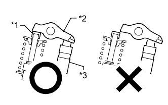
Make sure of the marks and numbers on the camshaft bearing caps and place them in each proper position and direction.
| *1 | Knock Pin |
| *2 | Camshaft |
 |
Tighten the 10 bolts in the order shown in the illustration.
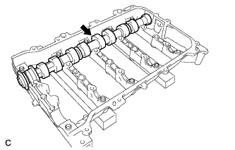
| 23. INSTALL CAMSHAFT HOUSING SUB-ASSEMBLY |
 |
Check that the valve rocker arms are installed as shown in the illustration.
| *1 | Valve Stem Cap |
| *2 | Valve Rocker Arm |
| *3 | Valve Lash Adjuster |
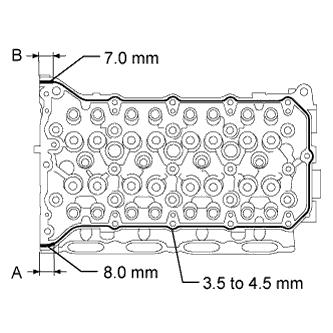 |
Apply seal packing in a continuous line as shown in the illustration.
| Area | Specified Condition |
| Continuous line | 3.5 to 4.5 mm (0.138 to 0.177 in.) |
| A | 8.0 mm (0.315 in.) |
| B | 7.0 mm (0.276 in.) |
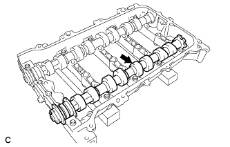
 |
Set the camshaft and No. 2 camshaft as shown in the illustration.
Install the camshaft housing with the 17 bolts and tighten them in the order shown in the illustration.
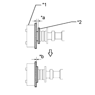
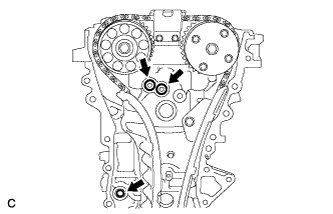
| 24. INSTALL CAMSHAFT TIMING SPROCKET |
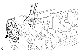 |
Tighten the flange bolt with the camshaft timing sprocket secured in place.
| 25. INSTALL CAMSHAFT TIMING GEAR ASSEMBLY |
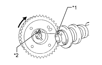 |
Put the camshaft timing gear and camshaft together with the straight pin and key groove misaligned as shown in the illustration.
| *1 | Straight Pin |
| *2 | Key Groove |
 |
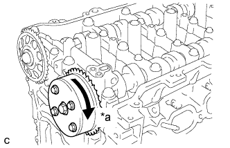
Turn the camshaft timing gear as shown in the illustration while pushing it gently against the camshaft. Push further at the position where the pin fits into the groove.
| *1 | Straight Pin |
| *2 | Key Groove |
 |
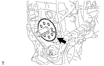
Check that there is no clearance between the camshaft timing gear and camshaft flange.
| *1 | Camshaft Timing Gear |
| *2 | Flange |
| *a | Clearance |
| *b | No Clearance |
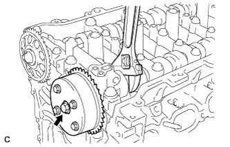 |
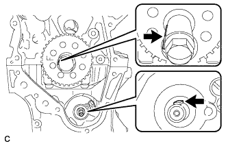
Tighten the flange bolt with the camshaft timing gear secured in place.
 |
Check that the camshaft timing gear can move in the retard direction (clockwise) and is locked in the most retarded position.
| *a | Lock |
| 26. INSTALL CRANKSHAFT TIMING GEAR KEY |
 |
Using a plastic-faced hammer, tap in the 2 crankshaft timing gear keys.
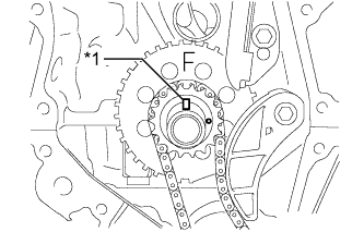
| 27. INSTALL NO. 1 CRANKSHAFT POSITION SENSOR PLATE |
 |
Install the crankshaft position sensor plate with the "F" mark facing forward.
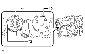
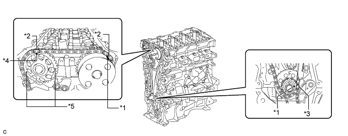
| 28. INSTALL NO. 2 CHAIN SUB-ASSEMBLY |
Temporarily install the crankshaft pulley bolt.
 |
Turn the crankshaft counterclockwise to position the timing gear key to the 9 o'clock position.
Turn the drive shaft so that the cutout faces the 12 o'clock position.
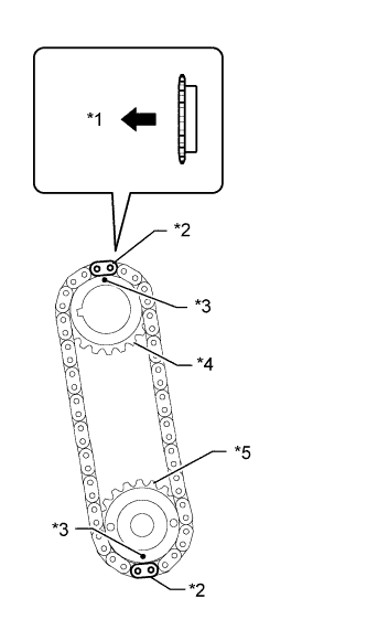 |
Align the yellow mark links with the timing marks of each gear as shown in the illustration.
| *1 | Front |
| *2 | Mark Plate (Yellow) |
| *3 | Timing Mark |
| *4 | Oil Pump Drive Gear |
| *5 | Oil Pump Drive Shaft Gear |
Install the sprockets onto the crankshaft and oil pump shaft with the chain on the gears.
Temporarily tighten the oil pump drive shaft gear with the nut.
 |
Insert the damper spring into the adjusting hole, and then install the chain tensioner plate with the bolt.
Temporarily tighten the crankshaft pulley with the bolt.
 |
Using SST, install the oil pump drive shaft gear nut while holding the crankshaft pulley.
Remove the crankshaft pulley and bolt.
| 29. INSTALL CRANKSHAFT TIMING SPROCKET |
 |
Install the crankshaft timing sprocket.
| 30. INSTALL NO. 1 CHAIN VIBRATION DAMPER |
 |
Install the chain vibration damper with the 2 bolts.
| 31. SET NO. 1 CYLINDER TO TDC/COMPRESSION |
 |
Temporarily install the crankshaft pulley bolt.
| *1 | Timing Gear Key |
Turn the crankshaft to position the timing gear key to the top.
 |
Check that the timing marks on the camshaft timing gear and camshaft timing sprocket are aligned as shown in the illustration.
| *1 | Timing Mark (Rectangle) |
| *2 | Timing Mark |
| *3 | Mark (Circle) |
Remove the crankshaft pulley bolt.
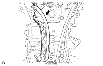
| 32. INSTALL CHAIN SUB-ASSEMBLY |
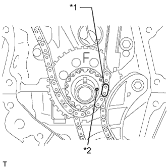
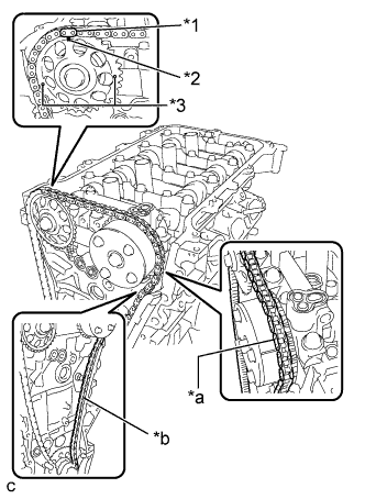 |
Align the mark plate (orange) with the timing mark as shown in the illustration and install the chain.
| *1 | Mark Plate (Orange) |
| *2 | Timing Mark (Rectangle) |
| *3 | Mark (Circle) |
| *a | Place the Chain on the Sprocket |
| *b | Pass the Chain through the Damper |
 |
Place the chain on the crankshaft without passing it around the shaft.
 |
Hold the hexagonal portion of the camshaft with a wrench and turn the camshaft timing gear counterclockwise to align the mark plate (orange) and timing mark, and then install the chain.
| *1 | Mark Plate (Orange) |
| *2 | Timing Mark |
| *a | Tension the Chain |
Hold the hexagonal portion of the camshaft with a wrench and turn the camshaft timing gear clockwise.
 |
Align the mark plate (yellow or pink) and timing mark and install the chain to the crankshaft timing gear.
| *1 | Mark Plate (Yellow or Pink) |
| *2 | Timing Mark |
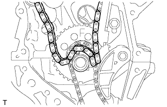
| 33. CHECK NO. 1 CYLINDER TO TDC/COMPRESSION |
Check each timing mark at TDC/compression.
| *1 | Timing Mark | *2 | Mark Plate (Orange) |
| *3 | Mark Plate (Yellow or Pink) | *4 | Timing Mark (Rectangle) |
| *5 | Mark (Circle) | - | - |
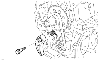
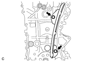
| 34. INSTALL CHAIN TENSIONER SLIPPER |
 |
Install the chain tensioner slipper to the cylinder block.
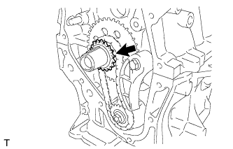
| 35. INSTALL NO. 2 CHAIN VIBRATION DAMPER |
 |
Install the No. 2 chain vibration damper with the 2 bolts.
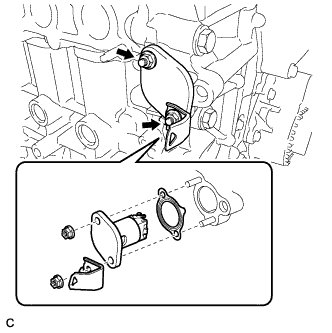
| 36. INSTALL INLET WATER SUB-ASSEMBLY STUD BOLT |
 |
Using an E5 "TORX" socket wrench, install the stud bolts as shown in the illustration.
| 37. INSTALL INLET WATER SUB-ASSEMBLY |
 |
Install a new gasket and the inlet water sub-assembly with the bolt and 2 nuts.
| 38. INSTALL TIMING CHAIN COVER SUB-ASSEMBLY |
Remove any old packing (FIPG) material and be careful not to drop any oil on the contact surfaces of the timing chain cover, cylinder head, and cylinder block.
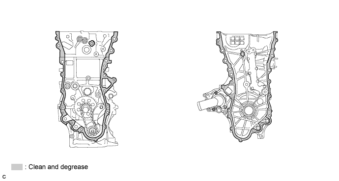
 |
Install 3 new O-rings.
Apply seal packing as shown in the illustration.
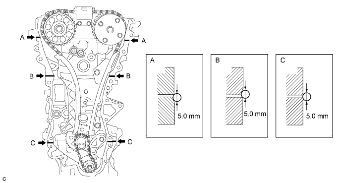
Apply seal packing to the timing chain cover in a line as shown in the following illustration.
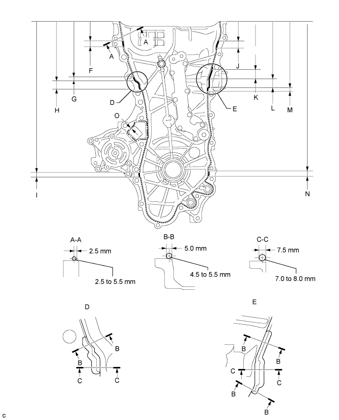
| Item | Seal Packing |
| Dashed line | Toyota Genuine Seal Packing Black, Three Bond 1207B or equivalent |
| Continuous line | |
| Alternate long and short dashed line | Toyota Genuine Seal Packing 1282B, Three Bond 1282B or equivalent |
| Area | Seal Packing Diameter | Distance from Edge of Cover to: | Seal Packing Application Length | Distance from Top of Cover to Top of Seal Packing |
| Dashed line | 2.5 to 3.0 mm (0.0984 to 0.118 in.) | Center of seal packing 2.5 mm (0.0984 in.) | - | - |
| Continuous line | 4.5 to 5.5 mm (0.177 to 0.217 in.) or 7.0 to 8.0 mm (0.276 to 0.315 in.) | - | - | - |
| Alternate long and short dashed line | 4.0 mm (0.157 in.) | Center of seal packing 3.0 mm (0.118 in.) | - | - |
| A - A | 2.5 to 3.0 mm (0.0984 to 0.118 in.) | Center of seal packing 2.5 mm (0.0984 in.) | - | - |
| B - B | 4.5 to 5.5 mm (0.177 to 0.217 in.) | Opposite edge of seal packing 5.0 mm (0.197 in.) | - | - |
| C - C | 7.0 to 8.0 mm (0.276 to 0.315 in.) | Opposite edge of seal packing 7.5 mm (0.295 in.) | - | - |
| F | 4.5 to 5.5 mm (0.177 to 0.217 in.) | - | 15.5 mm (0.610 in.) | 50.4 mm (1.98 in.) |
| G | 4.5 to 5.5 mm (0.177 to 0.217 in.) | - | 10.3 mm (0.406 in.) | 143.1 mm (5.63 in.) |
| H | 7.0 to 8.0 mm (0.276 to 0.315 in.) | - | 19.5 mm (0.768 in.) | 153.4 mm (6.04 in.) |
| I | 4.5 to 5.5 mm (0.177 to 0.217 in.) | - | 16.0 mm (0.630 in.) | 385.8 mm (1.27 ft.) |
| J | 4.5 to 5.5 mm (0.177 to 0.217 in.) | - | 18.6 mm (0.732 in.) | 51.4 mm (2.02 in.) |
| K | 4.5 to 5.5 mm (0.177 to 0.217 in.) | - | 25.3 mm (0.996 in.) | 121.9 mm (4.80 in.) |
| L | 7.0 to 8.0 mm (0.276 to 0.315 in.) | - | 25.8 mm (1.02 in.) | 147.2 mm (5.80 in.) |
| M | 4.5 to 5.5 mm (0.177 to 0.217 in.) | - | 5.1 mm (0.201 in.) | 173.0 mm (6.81 in.) |
| N | 4.5 to 5.5 mm (0.177 to 0.217 in.) | - | 14.6 mm (0.575 in.) | 385.8 mm (1.27 ft.) |
| O | 4.0 mm (0.157 in.) | Center of seal packing 3.0 mm (0.118 in.) | - | - |
Clean the bolt and fitting hole.
Install the timing chain cover.
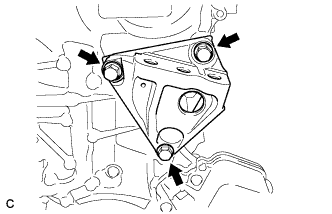 |
Temporarily tighten the engine mounting bracket RH with the 3 bolts.
| Item | Length |
| Bolt | 80 mm (3.15 in.) |
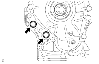 |
Install 2 new O-rings.
 |
Temporarily tighten the oil filter bracket with the 4 bolts.
| Item | Length |
| Bolt | 35 mm (1.38 in.) |
Install the timing chain cover with the 25 bolts and seal washer as shown in the illustration.
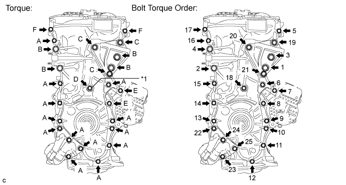
| *1 | Seal Washer | - | - |
| Item | Length |
| Bolt A, F | 35 mm (1.38 in.) |
| Bolt B | 55 mm (2.16 in.) |
| Bolt C | 80 mm (3.15 in.) |
| Bolt D | 40 mm (1.57 in.) |
| Bolt E | 55 mm (2.16 in.) |
| 39. INSTALL TIMING CHAIN COVER OIL SEAL |
Apply MP grease to the lip of a new oil seal.
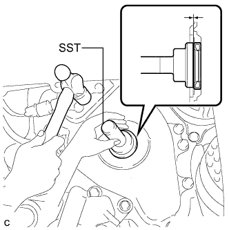 |
Using SST and a hammer, tap in the oil seal until its surface is flush with the front oil seal retainer edge.
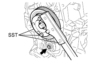
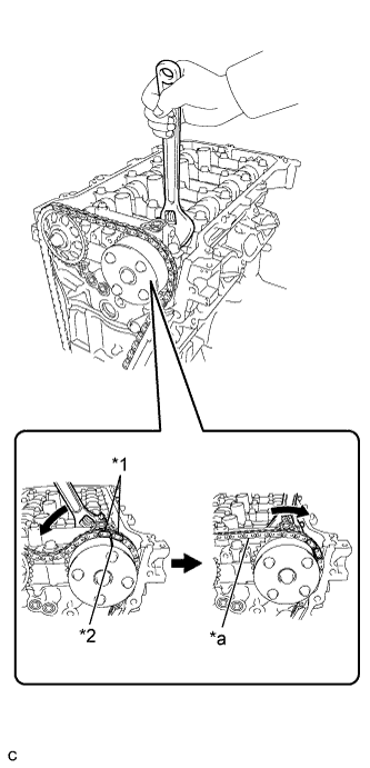
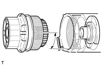
| 40. INSTALL CRANKSHAFT PULLEY |
Align the pulley set key with the key groove of the pulley.
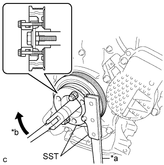 |
Using SST, hold the pulley in place and tighten the bolt.
| *a | Hold |
| *b | Turn |
| 41. INSTALL NO. 1 CHAIN TENSIONER ASSEMBLY |
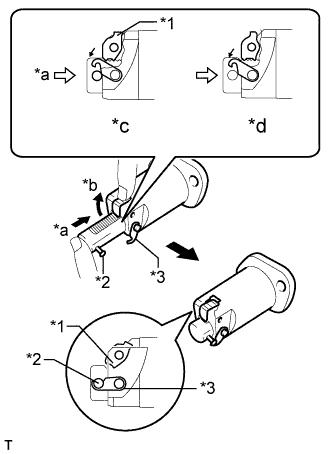 |
Release the cam, and then fully push in the plunger and engage the hook to the pin so that the plunger is in the position shown in the illustration.
| *1 | Cam |
| *2 | Pin |
| *3 | Hook |
| *a | Push |
| *b | Raise |
| *c | CORRECT |
| *d | INCORRECT |
 |
Install a new gasket, the bracket and chain tensioner with the 2 nuts.
 |
Rotate the crankshaft counterclockwise slightly and check that the hook becomes released.
| *1 | Pin |
| *2 | Hook |
| *a | Push |
| *b | Turn |
| *c | Disconnect |
 |
Turn the crankshaft clockwise and check that the plunger is extended.
| *1 | Plunger |
| *a | Turn |
| *b | Plunger Extended |
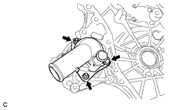
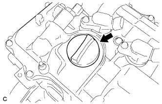
| 42. INSTALL OIL FILTER CAP ASSEMBLY |
Clean the oil filter cap threads and O-ring groove.
Apply a small amount of engine oil to a new O-ring and install it to the oil filter cap.
Set a new oil filter element in the oil filter cap.
Remove any dirt or foreign matter from the installation surface and inside of the engine.
 |
Reapply a small amount of engine oil to the O-ring of the oil filter cap assembly. Align the cutout in the oil filter cap threads 90° to the grooves in the oil filter bracket and temporarily tighten the cap.
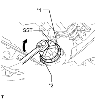 |
Using SST, tighten the oil filter cap assembly.
| *1 | No Clearance |
| *2 | Oil Filter Bracket Clip |
| 43. INSTALL SPARK PLUG TUBE GASKET |
 |
Using a cutter knife, cut off the seal part of the removed gasket.
 | Part to Cut Off |
 |
Using a hammer and the plug tube gasket which has had the sealing part cut off, uniformly tap in a new plug tube gasket all the way.
| *1 | Plug Tube Gasket without Sealing Part |
| *2 | New Plug Tube Gasket |
Return the claws of the ventilation baffle plate to their original positions.
| 44. INSTALL CYLINDER HEAD COVER GASKET |
 |
Install a new cylinder head cover gasket to the cylinder head cover.
| *1 | Cylinder Head Cover |
| *2 | Cylinder Head Cover Gasket |
| 45. INSTALL CYLINDER HEAD COVER SUB-ASSEMBLY |
 |
Install 2 new gaskets to the camshaft bearing cap.
 |
Apply seal packing as shown the illustration.
 |
Install the cylinder head cover with a new seal washer and the 13 bolts.
 |
| *1 | Timing Chain Cover |
| *2 | Camshaft Housing |
| *3 | Cylinder Head Cover Gasket |
| 46. INSTALL ENGINE OIL PRESSURE SWITCH ASSEMBLY |
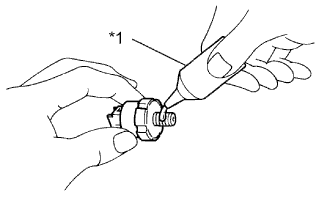 |
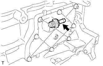
Apply adhesive to 2 or 3 threads of the engine oil pressure switch assembly.
| *1 | Adhesive |
 |
Using a 24 mm deep socket wrench, install the engine oil pressure switch assembly.
| 47. INSTALL ENGINE COOLANT TEMPERATURE SENSOR |
 |
Install a new gasket and the engine coolant temperature sensor.
| 48. INSTALL KNOCK SENSOR |
 |
Install the knock sensor with the bolt.
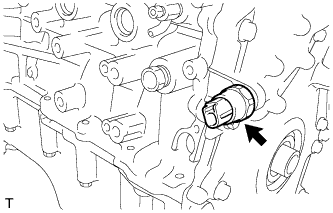
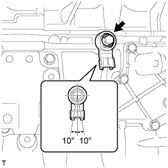
| 49. INSTALL CRANKSHAFT POSITION SENSOR |
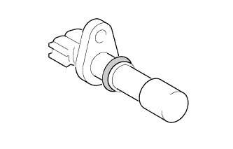 |
Apply a light coat of engine oil to the O-ring of the sensor.
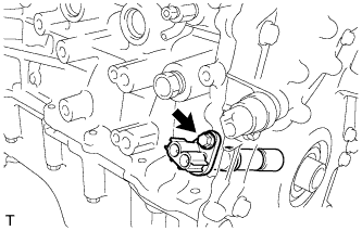 |
Install the crankshaft position sensor with the bolt.
| 50. INSTALL CAMSHAFT TIMING OIL CONTROL VALVE ASSEMBLY |
 |
Apply a light coat of engine oil to a new O-ring and install it to the camshaft timing oil control valve.
 |
Install the camshaft timing oil control valve with the bolt.
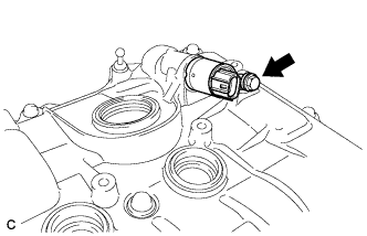
| 51. INSTALL CAMSHAFT POSITION SENSOR |
 |
Apply a light coat of engine oil to the O-ring of the sensor.
 |
Install the camshaft position sensor with the bolt.
| 52. INSTALL SPARK PLUG |
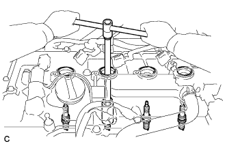 |
Using a 14 mm spark plug wrench, install the 4 spark plugs.
| 53. INSTALL ENGINE COVER JOINT BOLT |
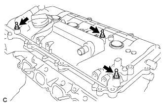 |
Install the 3 engine cover joint bolts.
| 54. INSTALL WIRING HARNESS CLAMP BRACKET |
 |
Install the wiring harness clamp bracket with the bolt.
| 55. INSTALL OIL FILLER CAP GASKET |
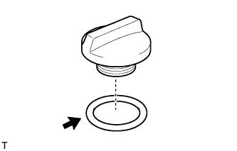 |
Install the gasket to the oil filler cap.
| 56. INSTALL OIL FILLER CAP SUB-ASSEMBLY |
 |
Install the oil filler cap.
