DTC B279A Theft Deterrent System Communication Line High Fixation |
| DTC No. | DTC Detection Condition | Trouble Area |
| B279A | When the communication line (EFIO - IMI) between power management control ECU (HV CPU) and certification ECU assembly (smart key ECU assembly)*1 or ID code box (immobiliser code ECU)*2 is stuck high output. |
|
| w/o Airbag Cut-off Switch |
| w/ Airbag Cut-off Switch |
| 1.CHECK DTC OUTPUT |
Clear the DTCs (Click here).
Recheck for DTCs (Click here).
| Result | Proceed to |
| DTC B279A is output | A |
| DTC B279A and other DTCs are output | B |
|
| ||||
| A | |
| 2.SYSTEM CHECK |
Check the vehicle specification.
| Result | Proceed to |
| w/o Airbag Cut-off Switch | A |
| w/ Airbag Cut-off Switch | B |
|
| ||||
| A | |
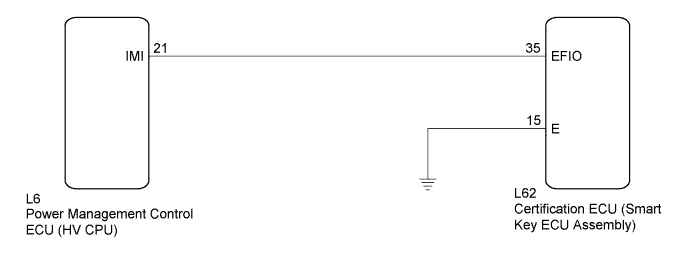
| 3.CHECK HARNESS AND CONNECTOR (CERTIFICATION ECU - POWER MANAGEMENT CONTROL ECU (HV CPU)) |
Disconnect the certification ECU (smart key ECU assembly) connector.
 |
Disconnect the power management control ECU (HV CPU) connector.
Measure the resistance and voltage according to the value(s) in the table below.
| Tester Connection | Condition | Specified Condition |
| L62-35 (EFIO) - L6-21 (IMI) | Always | Below 1 Ω |
| L6-21 (IMI) - Body ground | Always | 10 kΩ or higher |
| Tester Connection | Condition | Specified Condition |
| L6-21 (IMI) - Body ground | Always | Below 1 V |
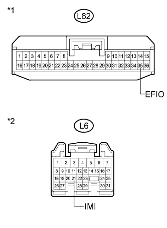
| *1 | Front view of wire harness connector (to Certification ECU (Smart Key ECU Assembly)) |
| *2 | Front view of wire harness connector (to Power Management Control ECU (HV CPU)) |
|
| ||||
| OK | |
| 4.CHECK CERTIFICATION ECU (SMART KEY ECU ASSEMBLY) (WAVEFORM) |
Reconnect the certification ECU (smart key ECU assembly) connector.
Reconnect the power management control ECU (HV CPU) connector.
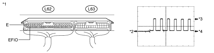
Using an oscilloscope, check the waveform.
| Item | Content |
| Terminal No. (Symbol) | L62-35 (EFIO) - L62-15 (E) |
| Tool Setting | 5 V/DIV., 50 msec./DIV. |
| Condition | Power switch on (IG) |
| *1 | Component with harness connected (Certification ECU (Smart Key ECU Assembly)) | *2 | GND |
| *3 | HIGH | *4 | LOW |
|
| ||||
| OK | ||
| ||
| 5.REPLACE CERTIFICATION ECU (SMART KEY ECU ASSEMBLY) |
Replace the certification ECU (smart key ECU assembly).
| NEXT | |
| 6.KEY REGISTRATION |
Register the key.
| NEXT | |
| 7.ECU COMMUNICATION ID REGISTRATION |
Register the ECU communication ID.
| NEXT | |
| 8.CHECK DTC OUTPUT |
Clear the DTCs (Click here).
Recheck for DTCs (Click here).
|
| ||||
| OK | ||
| ||
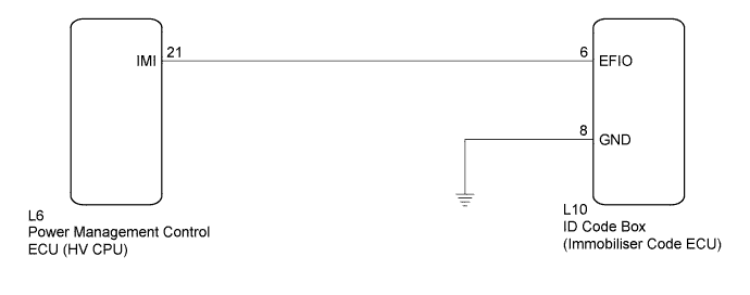
| 9.CHECK HARNESS AND CONNECTOR (ID CODE BOX - POWER MANAGEMENT CONTROL ECU (HV CPU)) |
Disconnect the ID code box (immobiliser code ECU) connector.
 |
Disconnect the power management control ECU (HV CPU) connector.
Measure the resistance and voltage according to the value(s) in the table below.
| Tester Connection | Condition | Specified Condition |
| L10-6 (EFIO) - L6-21 (IMI) | Always | Below 1 Ω |
| L6-21 (IMI) - Body ground | Always | 10 kΩ or higher |
| Tester Connection | Condition | Specified Condition |
| L6-21 (IMI) - Body ground | Always | Below 1 V |
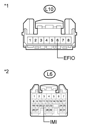
| *1 | Front view of wire harness connector (to ID Code Box (Immobiliser Code ECU)) |
| *2 | Front view of wire harness connector (to Power Management Control ECU (HV CPU)) |
|
| ||||
| OK | |
| 10.CHECK ID CODE BOX (IMMOBILISER CODE ECU) (WAVEFORM) |
Reconnect the ID code box (immobiliser code ECU) connector.
 |
Reconnect the power management control ECU (HV CPU) connector.
Using an oscilloscope, check the waveform.
| Item | Content |
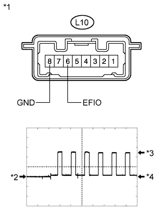
| Terminal No. (Symbol) | L10-6 (EFIO) - L10-8 (GND) |
| Tool Setting | 5 V/DIV., 50 msec./DIV. |
| Condition | Power switch on (IG) |
| *1 | Component with harness connected (ID Code Box (Immobiliser Code ECU)) |
| *2 | GND |
| *3 | HIGH |
| *4 | LOW |
|
| ||||
| OK | ||
| ||
| 11.REPLACE ID CODE BOX (IMMOBILISER CODE ECU) |
Replace the ID code box (immobiliser code ECU).
| NEXT | |
| 12.ECU CODE REGISTRATION |
Register the ECU code.
| NEXT | |
| 13.ECU COMMUNICATION ID REGISTRATION |
Register the ECU communication ID.
| NEXT | |
| 14.CHECK DTC OUTPUT |
Clear the DTCs (Click here).
Recheck for DTCs (Click here).
|
| ||||
| OK | ||
| ||
