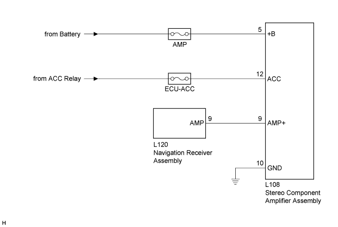
NAVIGATION SYSTEM (for HDD) > Stereo Component Amplifier Power Source Circuit |
| 1.INSPECT STEREO COMPONENT AMPLIFIER ASSEMBLY |
 |
Disconnect the L108 stereo component amplifier assembly connector.
Measure the resistance according to the value(s) in the table below .
| Tester Connection | Condition | Specified Condition |
| L108-10 (GND) - Body ground | Always | Below 1 Ω |
Measure the voltage according to the value(s) in the table below.
| Tester Connection | Condition | Specified Condition |
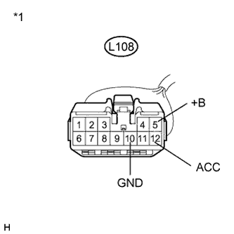
| L108-5 (+B) - L108-10 (GND) | Power switch off | 11 to 14 V |
| L108-12 (ACC) - L108-10 (GND) | Power switch on (ACC) | 11 to 14 V |
| *1 | Front view of wire harness connector (to Stereo Component Amplifier Assembly) |
|
| ||||
| OK | |
| 2.INSPECT STEREO COMPONENT AMPLIFIER ASSEMBLY |
 |
Disconnect the L108 stereo component amplifier assembly connector.
Measure the voltage according to the value(s) in the table below.
| Tester Connection | Condition | Specified Condition |
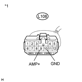
| L108-9 (AMP+) - L108-10 (GND) | Power switch on (IG) Audio system playing | 8 V or higher |
| *1 | Front view of wire harness connector (to Stereo Component Amplifier Assembly) |
|
| ||||
| OK | ||
| ||
| 3.CHECK HARNESS AND CONNECTOR (STEREO COMPONENT AMPLIFIER - NAVIGATION RECEIVER ASSEMBLY) |
 |
Disconnect the L108 stereo component amplifier assembly connector.
 |
Disconnect the L120 navigation receiver assembly connector.
Measure the resistance according to the value(s) in the table below.
| Tester Connection | Condition | Specified Condition |
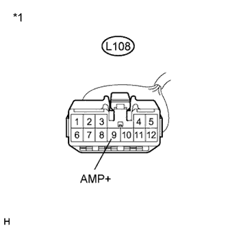
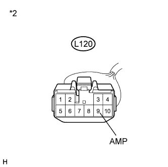
| L108-9 (AMP+) - L120-9 (AMP) | Always | Below 1 Ω |
| L108-9 (AMP+) - Body ground | Always | 10 kΩ or higher |
| *1 | Front view of wire harness connector (to Stereo Component Amplifier Assembly) |
| *2 | Front view of wire harness connector (to Navigation Receiver Assembly) |
|
| ||||
| OK | ||
| ||
