DTC U110B Lost Communication with Parking Assist Control Module "B" |
| DTC No. | DTC Detection Condition | Trouble Area |
| U110B | No communication from the parking assist ECU continues. |
|
| 1.RECONFIRM DTC OUTPUT |
Reconfirm DTCs.
| Result | Proceed to |
| U1002 is not output from power management control ECU (Intelligent tester display/Power Management1) | A |
| U1002 is output from power management control ECU (Intelligent tester display/Power Management1) | B |
|
| ||||
| A | |
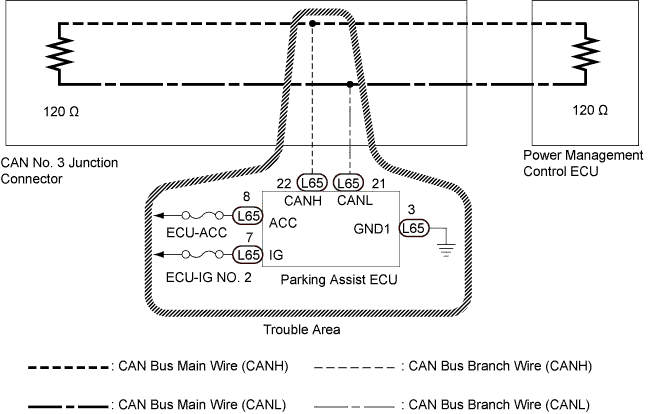
| 2.CHECK CAN BUS WIRE FOR DISCONNECTION (PARKING ASSIST ECU BRANCH WIRE) |
Turn the power switch off.
 |
Disconnect the parking assist ECU connector.
| *1 | Front view of wire harness connector (to Parking Assist ECU) |
Measure the resistance according to the value(s) in the table below.
| Tester Connection | Switch Condition | Specified Condition |
| L65-22 (CANH) - L65-21 (CANL) | Power switch off | 54 to 69 Ω |
|
| ||||
| OK | |
| 3.CHECK HARNESS AND CONNECTOR (POWER SOURCE TERMINAL) |
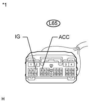 |
Measure the voltage according to the value(s) in the table below.
| Tester Connection | Switch Condition | Specified Condition |
| L65-8 (ACC) - Body ground | Power switch on (ACC) | 11 to 14 V |
| L65-7 (IG) - Body ground | Power switch on (IG) | 11 to 14 V |
| *1 | Front view of wire harness connector (to Parking Assist ECU) |
|
| ||||
| OK | |
| 4.CHECK HARNESS AND CONNECTOR (GROUND TERMINAL) |
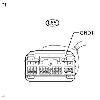 |
Measure the resistance according to the value(s) in the table below.
| Tester Connection | Condition | Specified Condition |
| L65-3 (GND1) - Body ground | Always | Below 1 Ω |
| *1 | Front view of wire harness connector (to Parking Assist ECU) |
|
| ||||
| OK | ||
| ||
