DTC U1002 Lost Communication with Gateway Module (Parking Assist Bus) |
| DTC No. | DTC Detection Condition | Trouble Area |
| U1002 | Driving support ECU cannot receive signals from all ECUs that have been memorized as those connected to the parking assist bus. |
|
| 1.CHECK CAN BUS WIRE |
Turn the power switch off.
 |
Measure the resistance according to the value(s) in the table below.
| Tester Connection | Switch Condition | Specified Condition | Result |
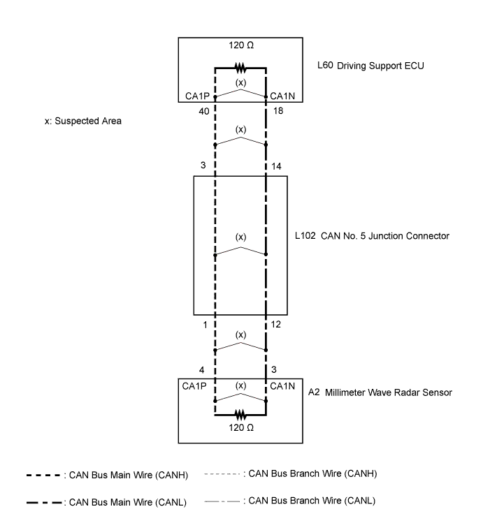
| L60-40 (CA1P) - L60-18 (CA1N) | Power switch off | 54 to 69 Ω | Below 54 Ω: Short circuit between bus lines |
| 70 Ω or more: Open circuit in a main bus line | |||
| L60-40 (CA1P) - L60-25 (GND) | Power switch off | 200 Ω or higher | Below 200 Ω: CANH ground short |
| L60-18 (CA1N) - L60-25 (GND) | Power switch off | 200 Ω or higher | Below 200 Ω: CANL ground short |
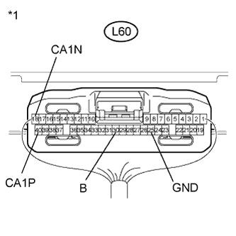
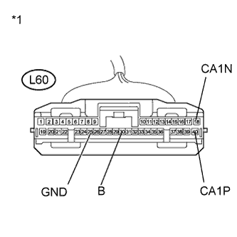
| *1 | Component with harness connected (Driving Support ECU) |
Disconnect the cable from the negative (-) battery terminal.
Measure the resistance according to the value(s) in the table below.
| Tester Connection | Condition | Specified Condition | Result |
| L60-40 (CA1P) - L60-30 (B) | Cable disconnected from negative (-) battery terminal | 6 kΩ or higher | Below 6 kΩ: CANH +B short |
| L60-18 (CA1N) - L60-30 (B) | Cable disconnected from negative (-) battery terminal | 6 kΩ or higher | Below 6 kΩ: CANL +B short |
| Result | Proceed to |
| OK | A |
| B |
| C |
|
| ||||
|
| ||||
| A | |
| 2.CHECK CAN BUS BRANCH WIRE (MILLIMETER WAVE RADAR SENSOR) |
Check for a millimeter wave radar sensor communication malfunction (Click here).
|
| ||||
| OK | ||
| ||
| 3.CHECK FOR OPEN IN CAN BUS WIRE (DRIVING SUPPORT ECU) |
 |
Disconnect the driving support ECU connector.
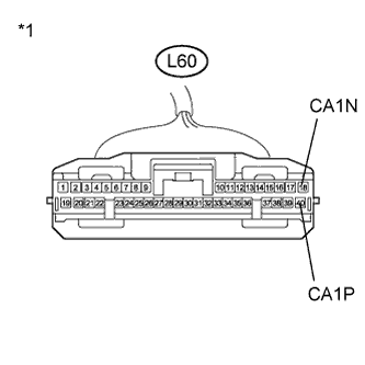
| *1 | Front view of wire harness connector (to Driving Support ECU) |
Measure the resistance according to the value(s) in the table below.
| Tester Connection | Switch Condition | Specified Condition |
| L60-40 (CA1P) - L60-18 (CA1N) | Power switch off | 108 to 132 Ω |
|
| ||||
| OK | ||
| ||
| 4.CHECK FOR OPEN IN CAN BUS WIRE (MILLIMETER WAVE RADAR SENSOR) |
Reconnect the driving support ECU connector.
 |
Disconnect the millimeter wave radar sensor connector.
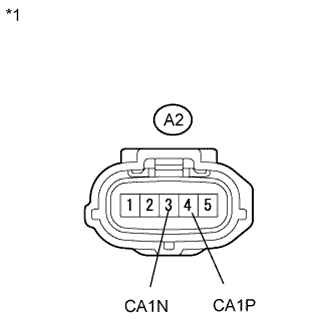
| *1 | Front view of wire harness connector (to Millimeter Wave Radar Sensor) |
Measure the resistance according to the value(s) in the table below.
| Tester Connection | Switch Condition | Specified Condition |
| A2-4 (CA1P) - A1-3 (CA1N) | Power switch off | 108 to 132 Ω |
|
| ||||
| OK | ||
| ||
| 5.CHECK FOR OPEN IN CAN BUS WIRE (CAN NO. 5 J/C) |
Reconnect the millimeter wave radar sensor connector.
 |
Disconnect the CAN No. 5 junction connector.
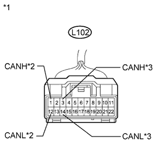
| *1 | Front view of wire harness connector (to CAN No. 5 Junction Connector) |
| *2 | to Millimeter Wave Radar Sensor |
| *3 | to Driving Support ECU |
Measure the resistance according to the value(s) in the table below.
| Tester Connection | Switch Condition | Specified Condition | Connected to |
| L102-1 (CANH) - L102-12 (CANL) | Power switch off | 108 to 132 Ω | Millimeter wave radar sensor |
| L102-3 (CANH) - L102-14 (CANL) | Power switch off | 108 to 132 Ω | Driving support ECU |
| Result | Proceed to |
| OK | A |
| NG (to driving support ECU) | B |
| NG (to millimeter wave radar sensor) | C |
|
| ||||
|
| ||||
| A | ||
| ||
| 6.CHECK FOR SHORT IN CAN BUS WIRES (DRIVING SUPPORT ECU) |
Disconnect the driving support ECU connector.
 |
Measure the resistance according to the value(s) in the table below.
| Tester Connection | Switch Condition | Specified Condition | Purpose |
| L60-40 (CA1P) - L60-25 (GND) | Power switch off | 200 Ω or higher | Below 200 Ω: CANH ground short |
| L60-18 (CA1N) - L60-25 (GND) | Power switch off | 200 Ω or higher | Below 200 Ω: CANL ground short |
| L60-40 (CA1P) - L60-30 (B) | Cable disconnected from negative (-) battery terminal | 6 kΩ or higher | Below 6 kΩ: CANH +B short |
| L60-18 (CA1N) - L60-30 (B) | Cable disconnected from negative (-) battery terminal | 6 kΩ or higher | Below 6 kΩ: CANL +B short |
| *1 | Front view of wire harness connector (to Driving Support ECU) |
|
| ||||
| OK | ||
| ||
| 7.CHECK CAN BUS WIRE (MILLIMETER WAVE RADAR SENSOR) |
Disconnect the millimeter wave radar sensor connector.
 |
Measure the resistance according to the value(s) in the table below.
| Tester Connection | Switch Condition | Specified Condition | Purpose |
| A2-4 (CA1P) - L61-4 (CG) | Power switch off | 200 Ω or higher | Below 200 Ω: CANH ground short |
| A2-3 (CA1N) - L61-4 (CG) | Power switch off | 200 Ω or higher | Below 200 Ω: CANL ground short |
| A2-4 (CA1P) - L61-16 (BAT) | Cable disconnected from negative (-) battery terminal | 6 kΩ or higher | Below 6 kΩ: CANH +B short |
| A2-3 (CA1N) - L61-16 (BAT) | Cable disconnected from negative (-) battery terminal | 6 kΩ or higher | Below 6 kΩ: CANL +B short |
| *1 | Front view of wire harness connector (to Millimeter Wave Radar Sensor) |
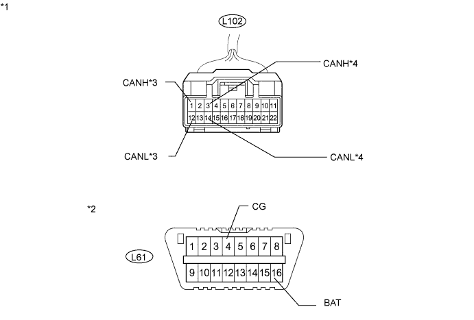
| *2 | DLC3 |
|
| ||||
| OK | ||
| ||
| 8.CHECK CAN BUS WIRE (CAN NO. 5 J/C) |
Disconnect the CAN No. 5 junction connector.
Measure the resistance according to the value(s) in the table below.
| Tester Connection | Condition | Specified Condition | Purpose | Connected to |
| L102-1 (CANH) - L61-4 (CG) | Power switch off | 200 Ω or higher | Inspection for CANH ground short | Millimeter wave radar sensor |
| L102-12 (CANL) - L61-4 (CG) | Power switch off | 200 Ω or higher | Inspection for CANL ground short | |
| L102-3 (CANH) - L61-4 (CG) | Power switch off | 200 Ω or higher | Inspection for CANH ground short | Driving support ECU |
| L102-14 (CANL) - L61-4 (CG) | Power switch off | 200 Ω or higher | Inspection for CANL ground short | |
| L102-1 (CANH) - L61-16 (BAT) | Cable disconnected from negative (-) battery terminal | 6 kΩ or higher | Inspection for CANH +B short | Millimeter wave radar sensor |
| L102-12 (CANL) - L61-16 (BAT) | Cable disconnected from negative (-) battery terminal | 6 kΩ or higher | Inspection for CANL +B short | |
| L102-3 (CANH) - L61-16 (BAT) | Cable disconnected from negative (-) battery terminal | 6 kΩ or higher | Inspection for CANH +B short | Driving support ECU |
| L102-14 (CANL) - L61-16 (BAT) | Cable disconnected from negative (-) battery terminal | 6 kΩ or higher | Inspection for CANL +B short |
| *1 | Front view of wire harness connector (to CAN No. 5 Junction Connector) | *2 | DLC3 |
| *3 | to Millimeter Wave Radar Sensor | *4 | to Driving Support ECU |
| Result | Proceed to |
| OK | A |
| NG (to driving support ECU) | B |
| NG (to millimeter wave radar sensor) | C |
|
| ||||
|
| ||||
| A | ||
| ||
