Home

Toyota Workshop

GSIC - Global Service Information Center

COMPRESSOR > REMOVAL

for Preparation Click here


1. PRECAUTION
(Click here)

NOTICE:
After the power switch is turned off, the display and navigation module display (HDD navigation system) records various types of memory and settings. As a result, after turning the power switch off, make sure to wait at least 60 seconds before disconnecting the cable from the negative (-) battery terminal.


2. RECOVER REFRIGERANT FROM REFRIGERATION SYSTEM
  1. Turn the A/C switch on.

  1. Operate the A/C with the setting temperature at 25°C (77°F) and the blower level at LO for 10 minutes to circulate the refrigerant. This causes most of the compressor oil from the various components of the A/C system to collect in the A/C compressor.

  1. Turn the power switch off.

  1. Recover the refrigerant from the A/C system using a refrigerant recovery unit.


3. REMOVE REAR NO. 2 FLOOR BOARD


    B227787E01
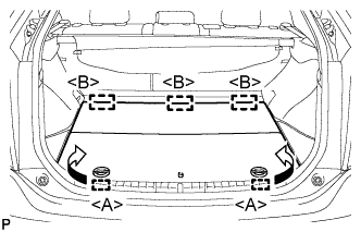
  1. Disengage the 2 guides <A> as shown in the illustration.

  1. Disengage the 3 guides <B> and remove the rear No. 2 floor board.


4. REMOVE REAR DECK FLOOR BOX
  1. Remove the rear deck floor box.


5. REMOVE REAR NO. 3 FLOOR BOARD


    B227791
  1. Disengage the 2 guides and remove the rear No. 3 floor board.


6. DISCONNECT CABLE FROM NEGATIVE BATTERY TERMINAL

NOTICE:
When disconnecting the cable, some systems need to be initialized after the cable is reconnected (Click here).


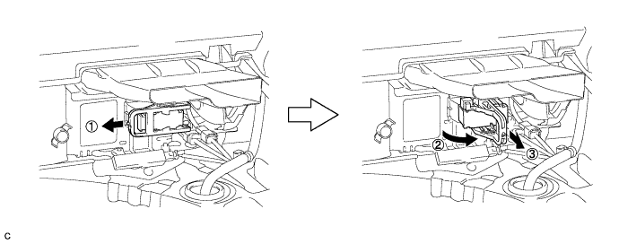
7. REMOVE SERVICE PLUG GRIP

CAUTION:
  1. Wear insulating gloves.
  2. Remove the service plug grip to interrupt the high voltage circuit at the time of inspection or repair.
  3. Keep the removed service plug grip in your pocket to prevent other technicians from accidentally reconnecting it while you are servicing the vehicle.
  4. All the high voltage wiring connectors are colored in orange.


  1. Wear insulating gloves and remove the service plug grip after sliding up the lever of the service plug grip as shown in the illustration.


    D103337

    CAUTION:
    1. Keep the removed service plug grip in your pocket to prevent other technicians from accidentally reconnecting it while you are servicing the vehicle.
    2. After removing the service plug grip, do not touch the high voltage connectors or terminals for 10 minutes.

    HINT:
    Waiting for at least 10 minutes is required to discharge the high-voltage capacitor inside the inverter with converter assembly.


8. REMOVE INVERTER TERMINAL COVER

CAUTION:
Wear insulating gloves.


    A209686
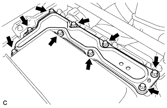
  1. Remove the 9 bolts and inverter terminal cover.

    NOTICE:
    Make sure to pull the inverter terminal cover straight up, as a connector is connected to the bottom of the cover.


9. CHECK TERMINAL VOLTAGE

CAUTION:
Wear insulating gloves.

NOTICE:
Do not allow any foreign objects or water to enter the inverter with converter assembly.


    A248051
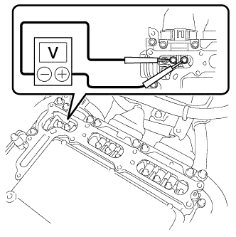
  1. Using a voltmeter, measure the voltage between the terminals of the 2 phase connectors.

    Standard voltage:
    0 V

    HINT:
    Use measuring range of DC 750 V or more on the voltmeter.


10. INSTALL INVERTER TERMINAL COVER


    A209686
  1. Temporarily install the inverter terminal cover with the 9 bolts to prevent any foreign objects or water from entering the inverter with converter assembly.


11. REMOVE INLET AIR CLEANER ASSEMBLY


    A269507
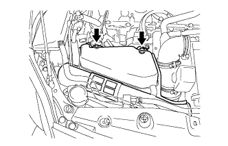
  1. Remove the 2 bolts and inlet air cleaner assembly.


12. REMOVE FRONT SPOILER COVER (w/ Front Spoiler)


13. REMOVE NO. 1 ENGINE UNDER COVER


14. DISCONNECT DISCHARGE HOSE SUB-ASSEMBLY


    E250822
  1. Remove the bolt and disconnect the discharge hose sub-assembly from the electric inverter compressor.

  1. Remove the O-ring from the discharge hose sub-assembly.

    NOTICE:
    Seal the openings of the disconnected parts using vinyl tape to prevent entry of moisture and foreign matter.


15. DISCONNECT SUCTION HOSE SUB-ASSEMBLY


    E250823
  1. Remove the bolt and disconnect the suction hose sub-assembly from the electric inverter compressor.

  1. Remove the O-ring from the suction hose sub-assembly.

    NOTICE:
    Seal the openings of the disconnected parts using vinyl tape to prevent entry of moisture and foreign matter.


16. REMOVE ELECTRIC INVERTER COMPRESSOR


    E241218E01
  1. Using a screwdriver, slide the green-colored lock of the connector <A> in the direction indicated by the arrow in the illustration to release it and disconnect the connector.
    Text in Illustration 
    *1
    Green-colored Lock

    CAUTION:
    Make sure to wear insulating gloves.

    NOTICE:
    Insulate the removed terminals and connector with insulating tape.

  1. Disconnect the connector <B>.


    E189091
  1. Remove the 3 bolts and electric inverter compressor.