COMPRESSOR > INSTALLATION |
| 1. ADJUST COMPRESSOR OIL |
 |
When replacing the electric inverter compressor with a new one, gradually discharge the refrigerant gas from the service valve, and drain the following amount of oil from the new electric inverter compressor before installation.
| 2. INSTALL ELECTRIC INVERTER COMPRESSOR |
 |
Temporarily install the electric inverter compressor with the 3 bolts.
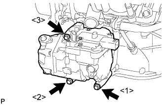 |
Install the electric inverter compressor with the 3 bolts.
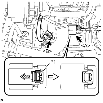 |
Connect the connector <B>.
| *1 | Green-colored Lock |
Connect the connector <A> and slide the green-colored lock in the direction indicated by the arrow in the illustration to lock it securely.
| 3. CONNECT SUCTION HOSE SUB-ASSEMBLY |
Remove the attached vinyl tape from the hose.
Sufficiently apply compressor oil to a new O-ring and the fitting surface of the compressor and magnetic clutch.
Install the O-ring onto the suction hose sub-assembly.
 |
Install the suction hose sub-assembly onto the compressor and magnetic clutch with the bolt.
| 4. CONNECT DISCHARGE HOSE SUB-ASSEMBLY |
Remove the attached vinyl tape from the hose.
Sufficiently apply compressor oil to a new O-ring and the fitting surface of the compressor and magnetic clutch.
Install the O-ring onto the discharge hose sub-assembly.
 |
Install the discharge hose sub-assembly onto the compressor and magnetic clutch with the bolt.
| 5. INSTALL SERVICE PLUG GRIP |
Wear insulated gloves and install the service plug grip in the order shown in the illustration.

Rotate the handle of the service plug grip 90° toward the battery and slide it in the direction shown by the arrow until a click sound is heard.
| 6. CONNECT CABLE TO NEGATIVE BATTERY TERMINAL |
| 7. INSTALL REAR NO. 3 FLOOR BOARD |
 |
Engage the 2 guides to install the rear No. 3 floor board.
| 8. INSTALL REAR DECK FLOOR BOX |
Install the rear deck floor box.
| 9. INSTALL REAR NO. 2 FLOOR BOARD |
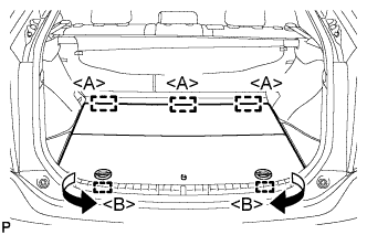 |
Engage the 3 guides <A>.
Engage the 2 guides <B> and install the rear No. 2 floor board as shown in the illustration.
| 10. CHARGE WITH REFRIGERANT |
Perform vacuum purging using a vacuum pump.
Charge with refrigerant HFC-134a (R134a).

| 11. WARM UP COMPRESSOR |
Keep the A/C switch on for at least 2 minutes to warm up the compressor.
| 12. INSPECT FOR REFRIGERANT LEAK |
After recharging with refrigerant, inspect for refrigerant leaks using a halogen leak detector.
Carry out the test under the following conditions:
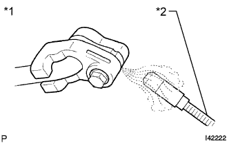 |
Using a halogen leak detector, inspect for refrigerant leaks from the refrigerant lines.
| *1 | Inspect for Leak |
| *2 | Halogen Leak Detector |
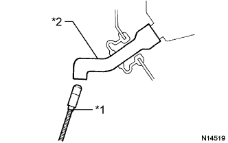 |
Bring the halogen leak detector close to the drain hose with the detector's power off, and then turn the detector on.
| *1 | Halogen Leak Detector |
| *2 | Drain Hose |
If a refrigerant leak is not detected from the drain hose, remove the blower motor control from the cooling unit. Insert the halogen leak detector sensor into the unit and perform the test.
Disconnect the pressure switch connector and leave it for approximately 20 minutes. Bring the halogen leak detector close to the pressure switch and perform the test.
| 13. INSTALL NO. 1 ENGINE UNDER COVER |
| 14. INSTALL FRONT SPOILER COVER (w/ Front Spoiler) |
| 15. INSTALL INLET AIR CLEANER ASSEMBLY |
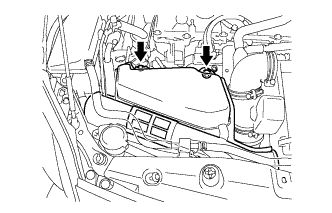 |
Install the inlet air cleaner assembly with the 2 bolts.
