DTC P0ADB-227 Hybrid Battery Positive Contactor Control Circuit Low |
| DTC No. | INF Code | DTC Detection Condition | Trouble Area |
| P0ADB | 227 | Short to GND in the SMRB circuit |
|
| 1.CHECK HARNESS AND CONNECTOR (POWER MANAGEMENT CONTROL ECU - BODY GROUND) |
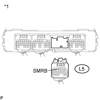
Disconnect connector L5 from the power management control ECU.
 |
Measure the resistance according to the value(s) in the table below.
| Tester Connection | Switch Condition | Specified Condition |
| L5-4 (SMRB) - Body ground | Power switch off | 19.0 to 35.5 Ω |
| *1 | Rear view of wire harness connector (to Power Management Control ECU) |
Connect the power management control ECU connector.
|
| ||||
| OK | ||
| ||
| 2.CHECK HARNESS AND CONNECTOR (POWER MANAGEMENT CONTROL ECU - HYBRID BATTERY JUNCTION BLOCK) |
Check that the service plug grip is not installed.
Remove the upper hybrid battery cover sub-assembly (Click here).
Disconnect connector c3 from the hybrid battery junction block.
Disconnect connector L5 from the power management control ECU.
 |
Measure the resistance according to the value(s) in the table below.
| Tester Connection | Switch Condition | Specified Condition |
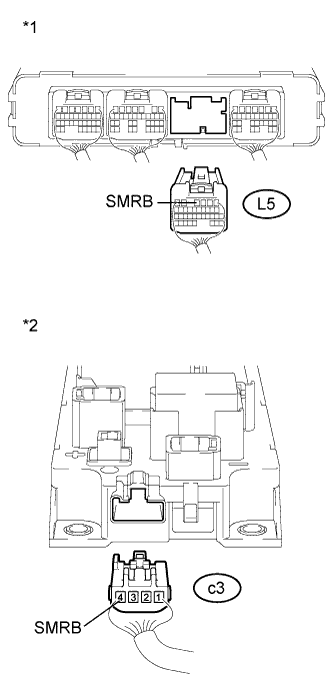
| L5-4 (SMRB) and c3-4 (SMRB) - Body ground and other terminals | Power switch off | 10 kΩ or higher |
| *1 | Rear view of wire harness connector (to Power Management Control ECU) |
| *2 | Rear view of wire harness connector (to Hybrid Battery Junction Block) |
Connect the power management control ECU connector.
Connect the hybrid battery junction block connector.
Install the upper hybrid battery cover sub-assembly (Click here).
|
| ||||
| OK | ||
| ||
