DTC P2237 Oxygen (A/F) Sensor Pumping Current Circuit / Open (Bank 1 Sensor 1) |
DTC P2238 Oxygen (A/F) Sensor Pumping Current Circuit Low (Bank 1 Sensor 1) |
DTC P2239 Oxygen (A/F) Sensor Pumping Current Circuit High (Bank 1 Sensor 1) |
DTC P2252 Oxygen (A/F) Sensor Reference Ground Circuit Low (Bank 1 Sensor 1) |
DTC P2253 Oxygen (A/F) Sensor Reference Ground Circuit High (Bank 1 Sensor 1) |
| DTC No. | DTC Detection Condition | Trouble Area |
| P2237 | Open in the circuit between terminals A1A+ and A1A- of the air fuel ratio sensor while engine is running (2 trip detection logic) |
|
| P2238 | Any of the following conditions are met (2 trip detection logic)
|
|
| P2239 | A1A+ voltage is more than 4.5 V (2 trip detection logic) |
|
| P2252 | A1A- voltage is 0.5 V or less (2 trip detection logic) |
|
| P2253 | A1A- voltage is more than 4.5 V (2 trip detection logic) |
|
| Tester Display (Sensor) | Injection Volume | Status | Voltage |
| AFS Voltage B1S1 (Air fuel ratio) | +25% | Rich | Less than 3.1 V |
| AFS Voltage B1S1 (Air fuel ratio) | -12.5% | Lean | More than 3.4 V |
| O2S B1S2 (Heated oxygen) | +25% | Rich | More than 0.55 V |
| O2S B1S2 (Heated oxygen) | -12.5% | Lean | Less than 0.4 V |
| Case | Air Fuel Ratio Sensor (Sensor 1) Output Voltage | Heated Oxygen Sensor (Sensor 2) Output Voltage | Main Suspected Trouble Area |
| 1 | 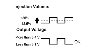 | 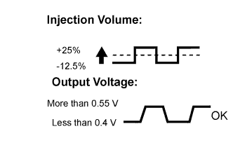 | - |
| 2 | 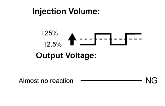 | |
|
| 3 | | 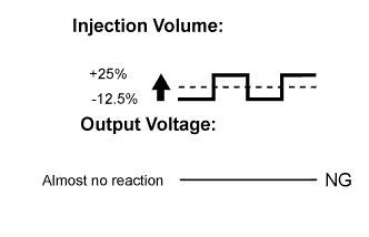 |
|
| 4 | | |
|
| 1.CHECK HARNESS AND CONNECTOR (AIR FUEL RATIO SENSOR - ECM) |
Disconnect the air fuel ratio sensor connector.
Disconnect the ECM connector.
Measure the resistance according to the value(s) in the table below.
| Tester Connection | Condition | Specified Condition |
| D24-1 (HA1A) - D28-18 (HA1A) | Always | Below 1 Ω |
| D24-3 (A1A+) - D28-103 (A1A+) | Always | Below 1 Ω |
| D24-4 (A1A-) - D28-126 (A1A-) | Always | Below 1 Ω |
| Tester Connection | Condition | Specified Condition |
| D24-1 (HA1A) or D28-18 (HA1A) - Body ground | Always | 10 kΩ or higher |
| D24-3 (A1A+) or D28-103 (A1A+) - Body ground | Always | 10 kΩ or higher |
| D24-4 (A1A-) or D28-126 (A1A-) - Body ground | Always | 10 kΩ or higher |
Reconnect the air fuel ratio sensor connector.
Reconnect the ECM connector.
|
| ||||
| OK | |
| 2.REPLACE AIR FUEL RATIO SENSOR NO.2 |
Replace the air fuel ratio sensor (Click here).
| NEXT | |
| 3.PERFORM CONFIRMATION DRIVING PATTERN |
Connect the intelligent tester to the DLC3.
Turn the power switch on (IG).
Turn the tester on.
Clear the DTCs.
Put the engine in inspection mode (Click here).
Start the engine and wait for 2 minutes.
| NEXT | |
| 4.CHECK WHETHER DTC OUTPUT RECURS |
Connect the intelligent tester to the DLC3.
Turn the power switch on (IG).
Turn the tester on.
Enter the following menus: Powertrain / Engine and ECT / DTC / Pending.
Read the Pending DTCs.
| Result | Proceed to |
| DTC is not output | A |
| DTC P2237, P2238, P2239, P2252 or P2253 is output | B |
|
| ||||
| A | ||
| ||
