DTC C1511 Torque Sensor Circuit Malfunction |
DTC C1512 Torque Sensor Circuit Malfunction |
DTC C1513 Torque Sensor Circuit Malfunction |
DTC C1514 Torque Sensor Power Supply Abnormal |
DTC C1517 Torque Hold Abnormal |
| DTC No. | DTC Detection Condition | Trouble Area |
| C1511 | Torque sensor malfunction |
|
| C1512 | ||
| C1513 | ||
| C1514 | ||
| C1517 |
| 1.CHECK CONNECTOR CONNECTION CONDITION (TORQUE SENSOR - ECU) |
Check the installation condition of the torque sensor connector.
|
| ||||
| OK | |
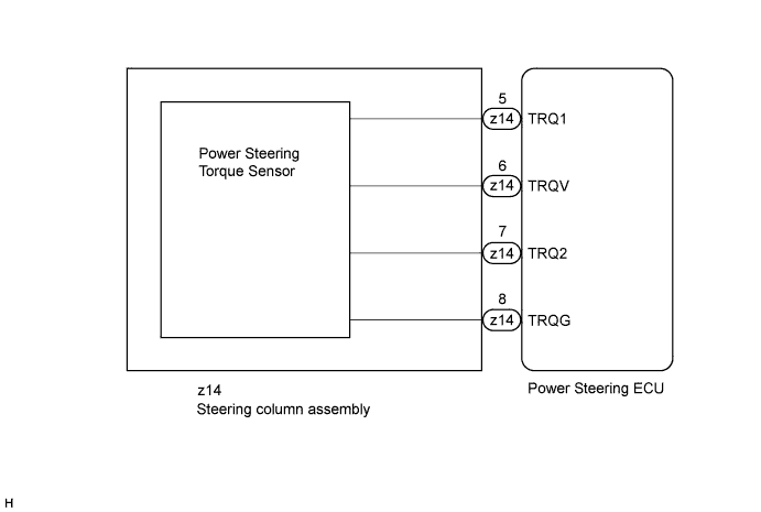
| 2.CHECK POWER STEERING ECU (TRQV VOLTAGE) |
 |
Turn the power switch on (READY).
Measure the voltage according to the value(s) in the table below.
| Tester Connection | Switch Condition | Specified Condition |
| z14-6 (TRQV) - z14-8 (TRQG) | Power switch on (READY) | 4.5 to 5.5 V |
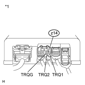
| *1 | Component with harness connected (Power Steering ECU) |
|
| ||||
| OK | |
| 3.CHECK POWER STEERING ECU (TRQ1, TRQ2 VOLTAGE) |
 |
Turn the power switch on (READY).
Measure the voltage according to the value(s) in the table below.
| Tester Connection | Switch Condition (Steering Wheel Position) | Specified Condition |
| z14-5 (TRQ1) - z14-8 (TRQG) | Power switch on (READY) Steering wheel not turned (without load) | 2.3 to 2.7 V |
| Power switch on (READY) Steering wheel turned to right with vehicle stopped | 2.5 to 3.8 V | |
| Power switch on (READY) Steering wheel turned to left with vehicle stopped | 1.2 to 2.5 V | |
| z14-7 (TRQ2) - z14-8 (TRQG) | Power switch on (READY) Steering wheel not turned (without load) | 2.3 to 2.7 V |
| Power switch on (READY) Steering wheel turned to right with vehicle stopped | 1.2 to 2.5 V | |
| Power switch on (READY) Steering wheel turned to left with vehicle stopped | 2.5 to 3.8 V |
Under each condition, measure the voltage at terminals TRQ1 and TRQ2, and calculate the sum.
| Inspection Item | Condition (Steering Wheel Position) | Specified Condition |
| Sum of voltage between z14-5 (TRQ1) and z14-8 (TRQG) and voltage between z14-7 (TRQ2) and z14-8 (TRQG) | Power switch on (READY) Steering wheel not being turned (without load) | Between 4.75 V and 5.25 V |
| Power switch on (READY) Steering wheel being turned to the right with vehicle stopped | ||
| Power switch on (READY) Steering wheel being turned to the left with vehicle stopped |
| *1 | Component with harness connected (Power Steering ECU) |
|
| ||||
| OK | ||
| ||
