SFI SYSTEM (w/ EGR System) > ECM Power Source Circuit |
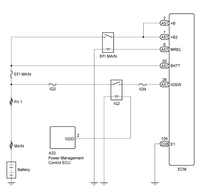
| 1.CHECK HARNESS AND CONNECTOR (ECM - BODY GROUND) |
 |
Disconnect the ECM connector.
Measure the resistance according to the value(s) in the table below.
| Tester Connection | Condition | Specified Condition |
| D28-104 (E1) - Body ground | Always | Below 1 Ω |
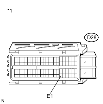
| *1 | Front view of wire harness connector (to ECM) |
Reconnect the ECM connector.
|
| ||||
| OK | |
| 2.INSPECT ECM (IGSW VOLTAGE) |
 |
Disconnect the ECM connector.
Turn the power switch on (IG).
Measure the voltage according to the value(s) in the table below.
| Tester Connection | Switch Condition | Specified Condition |
| A57-28 (IGSW) - Body ground | Power switch on (IG) | 11 to 14 V |
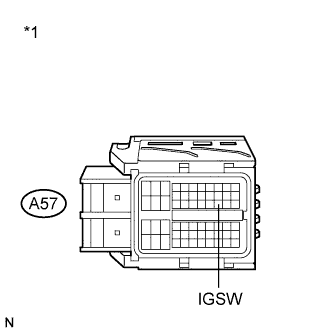
| *1 | Front view of wire harness connector (to ECM) |
Reconnect the ECM connector.
|
| ||||
| OK | |
| 3.INSPECT INTEGRATION RELAY (EFI MAIN RELAY) |
 |
Remove the integration relay from the engine room relay block.
Disconnect the integration relay connector.
Measure the resistance according to the value(s) in the table below.
| Tester Connection | Condition | Specified Condition |
| 1C-1 - 1B-4 | No battery voltage applied between terminals 1B-2 and 1B-3 | 10 kΩ or higher |
| Battery voltage applied between terminals 1B-2 and 1B-3 | Below 1 Ω |
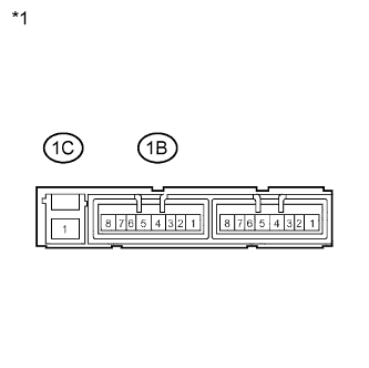
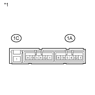
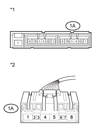
| *1 | Component without harness connected (Integration Relay) |
Reconnect the integration relay connector.
Reinstall the integration relay.
|
| ||||
| OK | |
| 4.CHECK HARNESS AND CONNECTOR (INTEGRATION RELAY (EFI MAIN RELAY) - ECM) |
Remove the integration relay from the engine room relay block.
Disconnect the integration relay connector.
Disconnect the ECM connector.
Measure the resistance according to the value(s) in the table below.
| Tester Connection | Condition | Specified Condition |
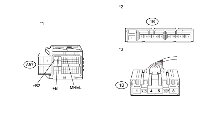
| 1B-4 - A57-1 (+B2) | Always | Below 1 Ω |
| 1B-4 - A57-2 (+B) | Always | Below 1 Ω |
| 1B-2 - A57-6 (MREL) | Always | Below 1 Ω |
| Tester Connection | Condition | Specified Condition |
| 1B-4 or A57-1 (+B2) - Body ground | Always | 10 kΩ or higher |
| 1B-4 or A57-2 (+B) - Body ground | Always | 10 kΩ or higher |
| 1B-2 or A57-6 (MREL) - Body ground | Always | 10 kΩ or higher |
| *1 | Front view of wire harness connector (to ECM) | *2 | Integration Relay |
| *3 | Front view of wire harness connector (to Integration Relay) | - | - |
Reconnect the ECM connector.
Reconnect the integration relay connector.
Reinstall the integration relay.
|
| ||||
| OK | |
| 5.CHECK HARNESS AND CONNECTOR (INTEGRATION RELAY (EFI MAIN RELAY) - BATTERY) |
 |
Remove the integration relay from the engine room relay block.
Disconnect the integration relay connector.
Disconnect the negative battery terminal.
Disconnect the positive battery terminal.
Measure the resistance according to the value(s) in the table below.
| Tester Connection | Condition | Specified Condition |
| 1C-1 - Battery positive terminal | Always | Below 1 Ω |
| Tester Connection | Condition | Specified Condition |
| 1C-1 or Battery positive terminal - Body ground | Always | 10 kΩ or higher |
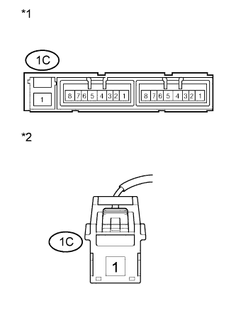
| *1 | Integration Relay |
| *2 | Front view of wire harness connector (to Integration Relay) |
Reconnect the integration relay connector.
Reinstall the integration relay.
Reconnect the positive battery terminal.
Reconnect the negative battery terminal.
|
| ||||
| OK | |
| 6.CHECK HARNESS AND CONNECTOR (INTEGRATION RELAY (EFI MAIN RELAY) - BODY GROUND) |
 |
Remove the integration relay from the engine room relay block.
Disconnect the integration relay connector.
Measure the resistance according to the value(s) in the table below.
| Tester Connection | Condition | Specified Condition |
| 1B-3 - Body ground | Always | Below 1 Ω |
| *1 | Integration Relay |
| *2 | Front view of wire harness connector (to Integration Relay) |
Reconnect the integration relay connector.
Reinstall the integration relay.
|
| ||||
| OK | ||
| ||
| 7.INSPECT INTEGRATION RELAY (IG2 RELAY) |
 |
Remove the integration relay from the engine room relay block.
Disconnect the integration relay connector.
Measure the resistance according to the value(s) in the table below.
| Tester Connection | Condition | Specified Condition |
| 1C-1 - 1A-4 | No battery voltage applied to terminals 1A-2 and 1A-3 | 10 kΩ or higher |
| Battery voltage applied to terminals 1A-2 and 1A-3 | Below 1 Ω |
| *1 | Component without harness connected (Integration Relay) |
Reconnect the integration relay connector.
Reinstall the integration relay.
|
| ||||
| OK | |
| 8.CHECK HARNESS AND CONNECTOR (INTEGRATION RELAY (IG2 RELAY) - ECM) |
Disconnect the ECM connector.
Remove the integration relay from the engine room relay block.
Disconnect the integration relay connector.
Measure the resistance according to the value(s) in the table below.
| Tester Connection | Condition | Specified Condition |
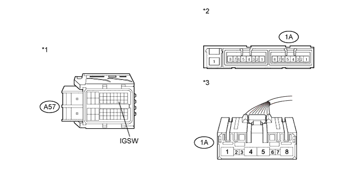
| 1A-4 - A57-28 (IGSW) | Always | Below 1 Ω |
| Tester Connection | Condition | Specified Condition |
| 1A-4 or A57-28 (IGSW) - Body ground | Always | 10 kΩ or higher |
| *1 | Front view of wire harness connector (to ECM) | *2 | Integration Relay |
| *3 | Front view of wire harness connector (to Integration Relay) | - | - |
Reconnect the ECM connector.
Reconnect the integration relay connector.
Reinstall the integration relay.
|
| ||||
| OK | |
| 9.CHECK HARNESS AND CONNECTOR (INTEGRATION RELAY (IG2 RELAY) - BATTERY) |
|
Remove the integration relay from the engine room relay block.
Disconnect the integration relay connector.
Disconnect the negative battery terminal.
Disconnect the positive battery terminal.
Measure the resistance according to the value(s) in the table below.
| Tester Connection | Condition | Specified Condition |
| 1C-1 - Battery positive terminal | Always | Below 1 Ω |
| Tester Connection | Condition | Specified Condition |
| 1C-1 or Battery positive terminal - Body ground | Always | 10 kΩ or higher |
| *1 | Integration Relay |
| *2 | Front view of wire harness connector (to Integration Relay) |
|
| ||||
| OK | |
| 10.CHECK HARNESS AND CONNECTOR (INTEGRATION RELAY (IG2 RELAY) - BODY GROUND) |
 |
Remove the integration relay from the engine room relay block.
Disconnect the integration relay connector.
Measure the resistance according to the value(s) in the table below.
| Tester Connection | Condition | Specified Condition |
| 1A-3 - Body ground | Always | Below 1 Ω |
| *1 | Integration Relay |
| *2 | Front view of wire harness connector (to Integration Relay) |
Reconnect the integration relay connector.
Reinstall the integration relay.
|
| ||||
| OK | |
| 11.CHECK HARNESS AND CONNECTOR (POWER MANAGEMENT CONTROL ECU - INTEGRATION RELAY (IG2 RELAY)) |
Remove the integration relay from the engine room relay block.

Disconnect the integration relay connector.
Disconnect the power management control ECU connector.
Measure the resistance according to the value(s) in the table below.
| Tester Connection | Condition | Specified Condition |
| A22-2 (IG2D) - 1A-2 | Always | Below 1 Ω |
| *1 | Front view of wire harness connector (to Power Management Control ECU) | *2 | Integration Relay |
| *3 | Front view of wire harness connector (to Integration Relay) | - | - |
Reconnect the integration relay connector.
Reinstall the integration relay.
Reconnect the power management control ECU connector.
|
| ||||
| OK | ||
| ||
