BACK DOOR > DISASSEMBLY |
| 1. REMOVE UPPER BACK DOOR TRIM PANEL ASSEMBLY |
 |
Using a moulding remover, disengage the 4 clips and 4 claws, and remove the upper back door trim panel assembly.
| 2. REMOVE BACK DOOR SIDE GARNISH RH |
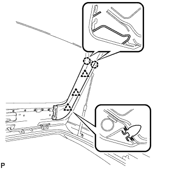 |
Disengage the 3 clips and 2 claws, and remove the back door side garnish RH.
| 3. REMOVE BACK DOOR SIDE GARNISH LH |
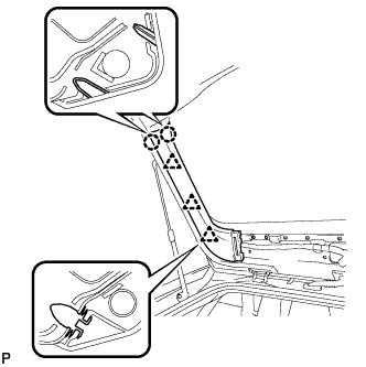 |
Disengage the 3 clips and 2 claws, and remove the back door side garnish LH.
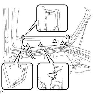
| 4. REMOVE BACK DOOR TRIM BOARD ASSEMBLY |
 |
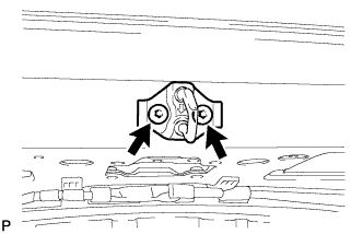
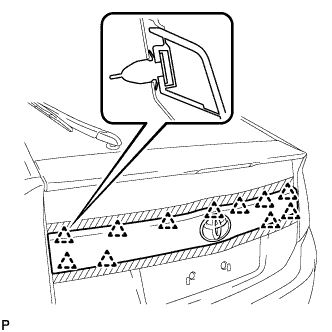
Using a moulding remover, disengage the clip and claw.
 |
Using a moulding remover, disengage the clip and claw.
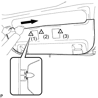 |
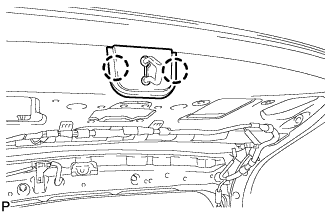
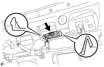
Disengage the 3 clips in the order shown in the illustration.
 |
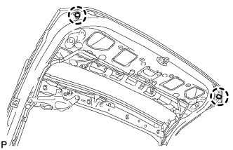
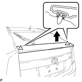
Disengage the 2 clips by pulling the back door trim board assembly in the direction indicated by the arrows in the illustration.
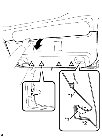 |
Remove the back door trim board assembly by pulling it in the direction indicated by the arrow in the illustration to disengage the 4 clips.
| *1 | Back Door Trim Board Assembly |
| *2 | Back Door Panel |
| *a | The portion that may be damaged due to interference |
| 5. REMOVE BACK DOOR TRIM BOARD |
 |
Disengage the 5 clips and 2 guides, and remove the back door trim board.
| 6. REMOVE BACK DOOR LOCK STRIKER COVER |
 |
Disengage the 2 claws and remove the back door lock striker cover.
| 7. REMOVE LOWER BACK DOOR STOPPER CUSHION |
 |
Disengage the claws to remove the 2 lower back door stopper cushions.
| 8. REMOVE BACK DOOR LOCK STRIKER ASSEMBLY |
 |
Using a T40 "TORX" socket wrench, remove the 2 screws and back door lock striker assembly.
| 9. REMOVE LOWER BACK DOOR STOPPER LH |
 |
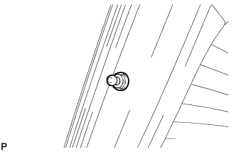
Remove the bolt and lower back door stopper LH.
| 10. REMOVE LOWER BACK DOOR STOPPER RH |
| 11. REMOVE BACK DOOR STAY ASSEMBLY LH |
 |
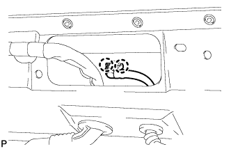
Using a screwdriver, remove the stop ring along the groove.
| *1 | Protective Tape |
Release the ball joint and remove the back door stay assembly.
| 12. REMOVE BACK DOOR STAY ASSEMBLY RH |
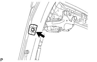
| 13. REMOVE BACK DOOR STAY BOLT LH |
 |
Remove the back door stay bolt.
| 14. REMOVE BACK DOOR STAY BOLT RH |
| 15. REMOVE BACK DOOR OUTSIDE GARNISH SUB-ASSEMBLY |
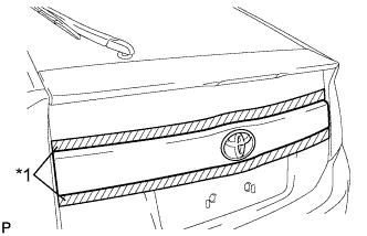 |
Put protective tape around the back door outside garnish sub-assembly.
| *1 | Protective Tape |
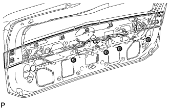 |
Remove the 4 nuts.
 |
Disengage the 11 clips and remove the back door outside garnish sub-assembly.
Remove the 11 clips (back door outside garnish clip) from the back door outside garnish sub-assembly.
Remove the 4 gaskets from the back door outside garnish sub-assembly.
| 16. REMOVE LICENSE PLATE LIGHT ASSEMBLY LH |
 |
Disconnect the connector.
Disengage the 2 claws and remove the license plate light assembly.
| 17. REMOVE LICENSE PLATE LIGHT ASSEMBLY RH |
| 18. REMOVE REAR SPOILER ASSEMBLY |
 |
Disconnect the connector.
Remove the 5 nuts.
 |
Disengage the 2 clips to remove the rear spoiler assembly.
| 19. REMOVE REAR WASHER NOZZLE |
 |
Disengage the 2 claws.
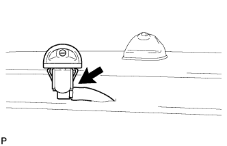 |
Disconnect the washer hose and remove the rear washer nozzle.
| 20. REMOVE REAR WIPER ARM HEAD CAP (w/ Resin Wiper Arm) |
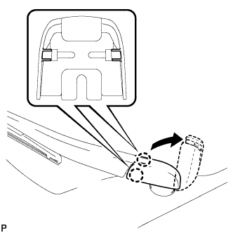 |
Disengage the 2 claws and open the rear wiper arm head cap as shown in the illustration.
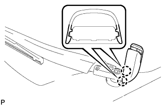 |
Disengage the 2 claws and remove the rear wiper arm head cap.
| 21. REMOVE REAR WIPER ARM AND BLADE ASSEMBLY |
w/ Resin Wiper Arm:
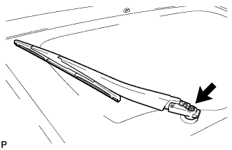 |
Remove the nut, and the rear wiper arm and blade assembly.
w/ Steel Wiper Arm:
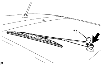 |
Open the rear wiper arm head cap.
| *1 | Rear Wiper Arm Head Cap |
Remove the nut and the rear wiper arm and blade assembly.
| 22. REMOVE REAR WIPER MOTOR GROMMET |
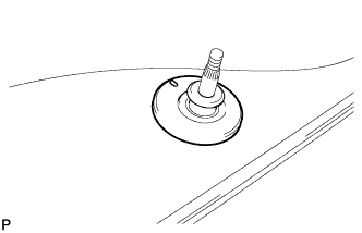 |
Remove the rear wiper motor grommet.
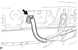
| 23. REMOVE REAR WIPER MOTOR ASSEMBLY |
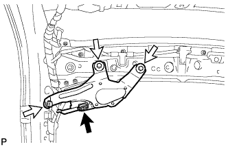 |
Disconnect the connector.
Remove the 3 bolts and the rear wiper motor assembly.
| 24. REMOVE REAR TELEVISION CAMERA ASSEMBLY (w/ Rear Monitor) |
 |
Disconnect the connector.
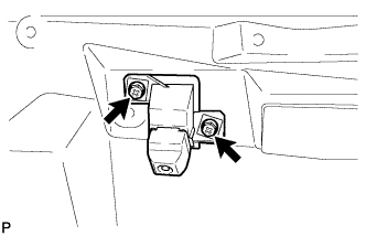 |
Remove the 2 screws.
 |
Disengage the 4 claws and remove the rear television camera assembly.
