SHIFT LEVER > INSTALLATION |
| 1. INSTALL SHIFT LOCK CONTROL UNIT ASSEMBLY |
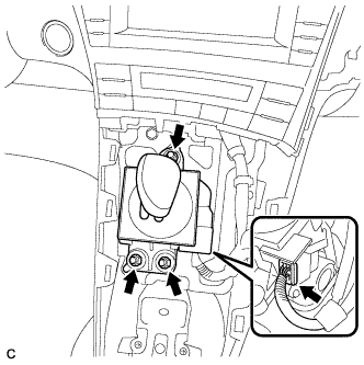 |
Install the shift lock control unit assembly with the 3 nuts.
Connect the connector to the shift lock control unit assembly.
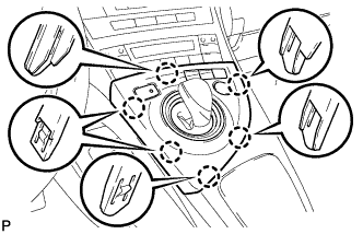
| 2. INSTALL LOWER CENTER INSTRUMENT CLUSTER FINISH PANEL SUB-ASSEMBLY |
 |
Engage the 7 claws and 2 clips to install the lower center instrument cluster finish panel sub-assembly.
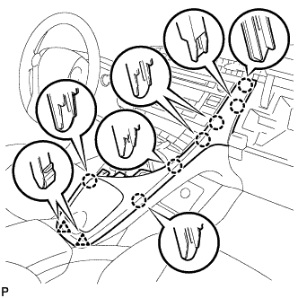
| 3. INSTALL INTEGRATION CONTROL AND PANEL ASSEMBLY |
 |
Connect each connector.
Engage the 6 claws to install the integration control and panel assembly.
| 4. INSTALL SHIFT LEVER KNOB |
Using a die (M6 x P1.00 mm), clean the threads of the shift control unit assembly.
 |
Turn the shift lever knob in the direction of the arrow in the illustration to install it.
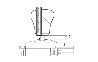 |
Using a vernier caliper, adjust the height of the shift lever knob.
| *1 | Measuring Point |
Remove the protective tape around the shift lock control unit assembly.
| 5. CONNECT CABLE TO NEGATIVE BATTERY TERMINAL |
| 6. INSTALL REAR NO. 3 FLOOR BOARD |
 |
Engage the 2 guides to install the rear No. 3 floor board.
| 7. INSTALL REAR DECK FLOOR BOX |
Install the rear deck floor box.
| 8. INSTALL REAR NO. 2 FLOOR BOARD |
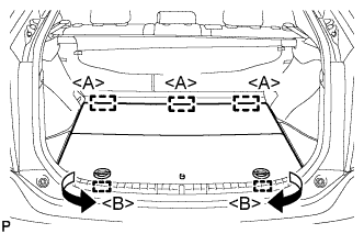 |
Engage the 3 guides <A>.
Engage the 2 guides <B> and install the rear No. 2 floor board as shown in the illustration.
| 9. INSPECT SHIFT LEVER |
Turn the power switch on (READY).
Check that all available shift positions can be selected moving the shift lever.
