AUDIO AND VISUAL SYSTEM > Voice Guidance Circuit between Radio Receiver and Stereo Component Amplifier |
| 1.CHECK HARNESS AND CONNECTOR (RADIO AND DISPLAY RECEIVER ASSEMBLY - STEREO COMPONENT AMPLIFIER ASSEMBLY) |
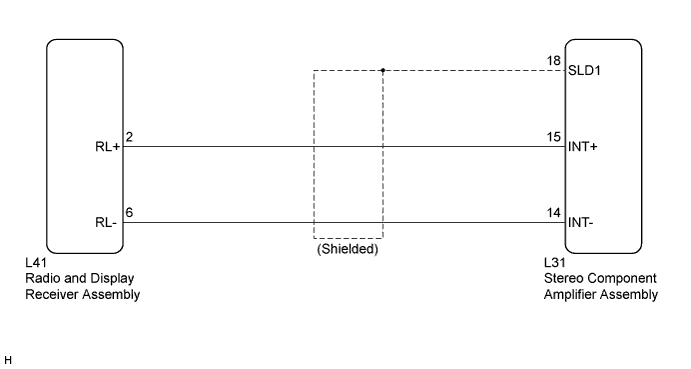
Disconnect the radio and display receiver assembly connector.
Disconnect the stereo component amplifier assembly connector.
Measure the resistance according to the value(s) in the table below.
| Tester connection | Condition | Specified condition |
| L147-2 (RL+) - L143-15 (II1+) | Always | Below 1 Ω |
| L147-6 (RL-) - L143-14 (II1-) | Always | Below 1 Ω |
| L143-18 (SLD1) - Body ground | Always | 10 kΩ or higher |
| L147-2 (RL+) - Body ground | Always | 10 kΩ or higher |
| L147-6 (RL-) - Body ground | Always | 10 kΩ or higher |
|
| ||||
| OK | ||
| ||
