ELECTRONIC SHIFT LEVER SYSTEM > "P" Position Switch Indicator Light Circuit |

| 1.CHECK TRANSMISSION SHIFT MAIN SWITCH (INDICATOR LIGHT) |
Turn the power switch on (IG).
Depress the brake pedal and move the selector lever to N.
Inspect the indicator light condition by operating the transmission shift main switch (P position switch).
| Condition of Indicator Light | Proceed to |
| Indicator light does not go off. (Remains on) | A |
| Indicator light does not come on. | B |
Turn the power switch off.
|
| ||||
| A | |
| 2.CHECK TRANSMISSION SHIFT MAIN SWITCH (INDICATOR LIGHT) |
Disconnect the A23 transmission control ECU assembly.
Turn the power switch on (IG).
Inspect the indicator light condition by operating the transmission shift main switch (P position switch).
| Condition of Indicator Light | Proceed to |
| Comes on | A |
| Does not come on | B |
Turn the power switch off.
Connect the transmission control ECU assembly connector.
|
| ||||
| A | |
| 3.CHECK HARNESS AND CONNECTOR (TRANSMISSION CONTROL ECU - TRANSMISSION SHIFT MAIN SWITCH) |
Disconnect the A23 transmission control ECU assembly connector.
Disconnect the b1 transmission shift main switch (P position switch) connector.
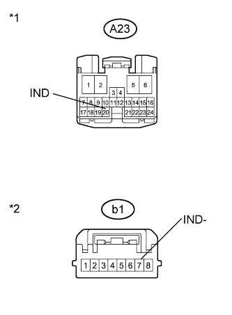 |
Measure the resistance according to the value(s) in the table below.
| Tester Connection | Switch Condition | Specified Condition |
| A23-20 (IND) or b1-7 (IND-) - Body ground and other terminals | Power switch off | 10 kΩ or higher |
| *1 | Front view of wire harness connector (to Transmission Control ECU Assembly) |
| *2 | Front view of wire harness connector (to Transmission Shift Main Switch (P Position Switch)) |
Connect the transmission shift main switch (P position switch) connector.
Connect the transmission control ECU assembly connector.
|
| ||||
| OK | ||
| ||
| 4.CHECK HARNESS AND CONNECTOR (TRANSMISSION SHIFT MAIN SWITCH POWER SOURCE CIRCUIT) |
Disconnect the b1 transmission shift main switch (P position switch) connector.
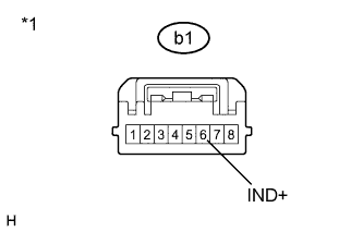 |
Measure the voltage according to the value(s) in the table below.
| Tester Connection | Switch Condition | Specified Condition |
| b1-6 (IND+) - Body ground | Power switch off | 9 to 14 V |
| *1 | Front view of wire harness connector (to Transmission Shift Main Switch (P Position Switch)) |
Connect the transmission shift main switch (P position switch) connector.
|
| ||||
| OK | |
| 5.INSPECT TRANSMISSION SHIFT MAIN SWITCH |
Disconnect the b1 transmission shift main switch (P position switch) connector.
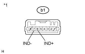 |
Apply auxiliary battery voltage between terminals b1-6 (IND+) and b1-7 (IND-) and check the indicator light.
| Condition | Specified Condition |
| Auxiliary battery voltage applied between terminals b1-6 (IND+) and b1-7 (IND-) | Comes on |
| *1 | Component without harness connected (Transmission Shift Main Switch (P Position Switch)) |
Connect the transmission shift main switch (P position switch) connector.
|
| ||||
| OK | |
| 6.CHECK HARNESS AND CONNECTOR (TRANSMISSION CONTROL ECU - TRANSMISSION SHIFT MAIN SWITCH) |
Disconnect the A23 transmission control ECU assembly connector.
Disconnect the b1 transmission shift main switch (P position switch) connector.
|
Measure the resistance according to the value(s) in the table below.
| Tester Connection | Switch Condition | Specified Condition |
| A23-20 (IND) - b1-7 (IND-) | Power switch off | Below 1 Ω |
| *1 | Front view of wire harness connector (to Transmission Control ECU Assembly) |
| *2 | Front view of wire harness connector (to Transmission Shift Main Switch (P Position Switch)) |
Connect the transmission shift main switch (P position switch) connector.
Connect the transmission control ECU assembly connector.
|
| ||||
| OK | ||
| ||
