HV BATTERY > REMOVAL |
| 1. PRECAUTION |
| 2. READ OUTPUT DTC |
Check for DTCs (Click here).
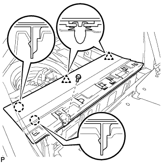
| 3. REMOVE REAR NO. 2 FLOOR BOARD |
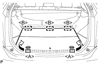 |
Disengage the 2 guides <A> as shown in the illustration.
Disengage the 3 guides <B> and remove the rear No. 2 floor board.
| 4. REMOVE REAR DECK FLOOR BOX |
Remove the rear deck floor box.
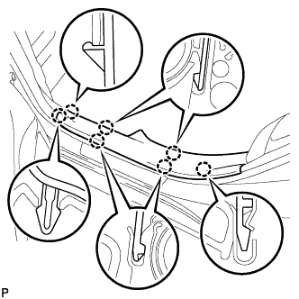
| 5. REMOVE REAR NO. 3 FLOOR BOARD |
 |
Disengage the 2 guides and remove the rear No. 3 floor board.
| 6. DISCONNECT CABLE FROM NEGATIVE BATTERY TERMINAL |
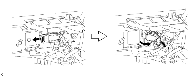
| 7. REMOVE SERVICE PLUG GRIP |
Wear insulating gloves and remove the service plug grip after sliding up the lever of the service plug grip as shown in the illustration.
| 8. REMOVE INVERTER TERMINAL COVER |
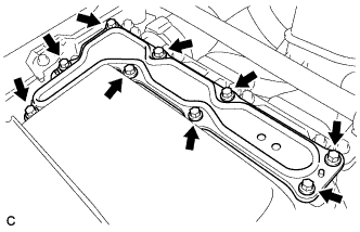 |
Remove the 9 bolts and inverter terminal cover.
| 9. CHECK TERMINAL VOLTAGE |
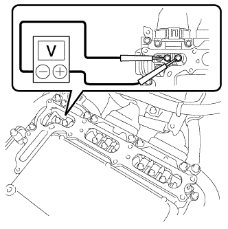 |
Using a voltmeter, measure the voltage between the terminals of the 2 phase connectors.
| 10. INSTALL INVERTER TERMINAL COVER |
 |
Install the inverter terminal cover with the 9 bolts to the inverter with converter assembly.
| *1 | Interlock |
| 11. REMOVE TONNEAU COVER ASSEMBLY (w/ Tonneau Cover) |
Remove the tonneau cover assembly.
| 12. REMOVE REAR SEAT CUSHION ASSEMBLY |
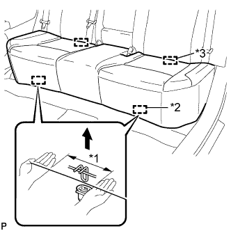 |
Disengage the 2 front hooks of the seat cushion from the vehicle body as shown in the illustration.
| *1 | 100 mm (3.94 in.) or less |
| *2 | Hook |
| *3 | Guide |
Choose a hook to detach first. Place your hands near the hook as shown in the illustration. Then lift the seat cushion to detach the hook.
Repeat the above procedure for the other hook.
Disengage the 2 guides of the seat cushion from the seatback.
Remove the rear seat cushion assembly.
| 13. REMOVE REAR NO. 1 FLOOR BOARD SUB-ASSEMBLY |
 |
Disengage the 2 claws and 2 clips, and remove the rear No. 1 floor board sub-assembly.
| 14. REMOVE REAR NO. 2 FLOOR BOARD SUB-ASSEMBLY |
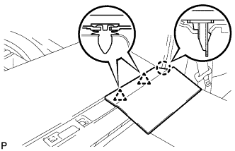 |
Disengage the claw and 2 clips, and remove the rear No. 2 floor board sub-assembly.
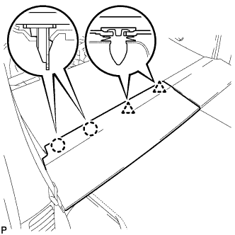
| 15. REMOVE REAR NO. 1 FLOOR BOARD |
 |
Remove the bolt.
Disengage the 2 claws and 2 clips, and remove the rear No. 1 floor board.
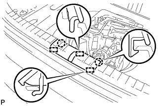
| 16. REMOVE REAR DOOR SCUFF PLATE LH |
 |
Disengage the 7 claws and remove the rear door scuff plate LH.
| 17. REMOVE REAR DOOR SCUFF PLATE RH |
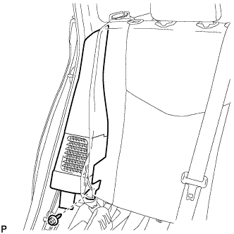
| 18. REMOVE REAR SIDE SEAT BACK ASSEMBLY LH |
 |
Remove the bolt.
 |
Disengage the 2 guides and remove the rear side seatback assembly LH as shown in the illustration.
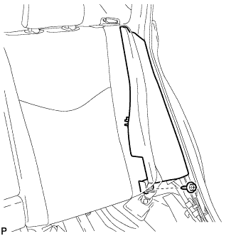
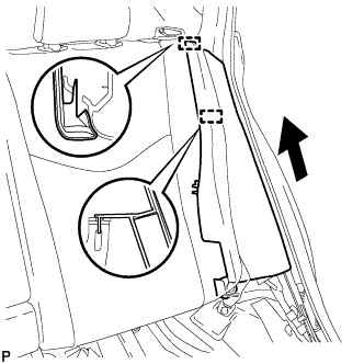
| 19. REMOVE REAR SIDE SEAT BACK ASSEMBLY RH |
 |
Remove the bolt.
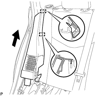 |
Disengage the 2 guides and remove the rear side seatback assembly RH as shown in the illustration.
| 20. REMOVE REAR NO. 4 FLOOR BOARD |
 |
Disengage the guide and remove the rear No. 4 floor board.
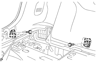
| 21. REMOVE DECK FLOOR BOX LH |
 |
Remove the clip.
Disengage the 2 guides and remove the deck floor box LH.
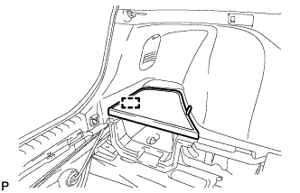
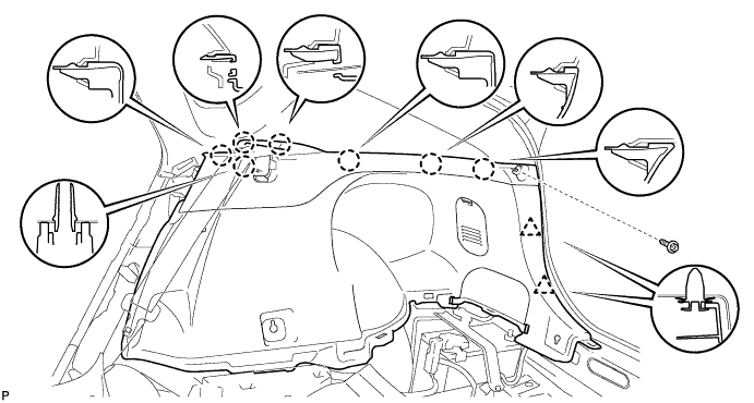
| 22. REMOVE DECK TRIM SERVICE HOLE COVER |
 |
Disengage the 2 claws and 3 guides, and remove the deck trim service hole cover.
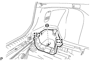
| 23. REMOVE REAR DECK TRIM COVER |
 |
Disengage the 4 claws and 4 guides, and remove the rear deck trim cover.
| 24. REMOVE LUGGAGE HOLD BELT STRIKER ASSEMBLY (for LH Side) |
 |
Remove the 2 bolts.
Disengage each guide and remove the 2 luggage hold belt striker assemblies.
| 25. REMOVE TONNEAU COVER HOLDER CAP (for LH Side) |
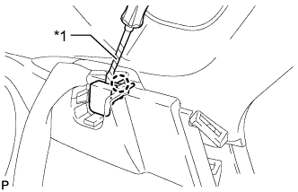 |
Using a screwdriver, disengage the claw and remove the tonneau cover holder cap.
| *1 | Protective Tape |
| 26. REMOVE DECK TRIM SIDE PANEL ASSEMBLY LH |
Remove the screw.
Disengage the 7 claws and 2 clips.
Disconnect the connector and remove the deck trim side panel assembly LH.

| 27. REMOVE TONNEAU COVER HOLDER CAP (for RH Side) |
| 28. REMOVE LUGGAGE HOLD BELT STRIKER ASSEMBLY (for RH Side) |
| 29. REMOVE DECK TRIM SIDE PANEL ASSEMBLY RH |
Remove the screw.
Disengage the 7 claws and 2 clips, and remove the deck trim side panel assembly RH.
| 30. REMOVE REAR FLOOR BOARD SPACER |
 |
Remove the 2 clips and rear floor board spacer.
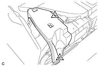
| 31. REMOVE NO. 1 HYBRID BATTERY EXHAUST DUCT |
 |
Remove the clip and No. 1 hybrid battery exhaust duct.
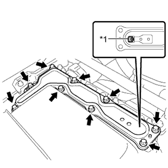
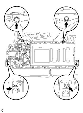
| 32. REMOVE UPPER HYBRID BATTERY COVER SUB-ASSEMBLY |
 |
Using the service plug grip, remove the battery cover lock striker.
Remove the 4 nuts and upper hybrid battery cover sub-assembly.
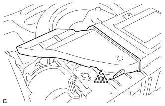
| 33. REMOVE NO. 1 HYBRID BATTERY INTAKE DUCT |
 |
Remove the 2 clips and No. 1 hybrid battery intake duct.
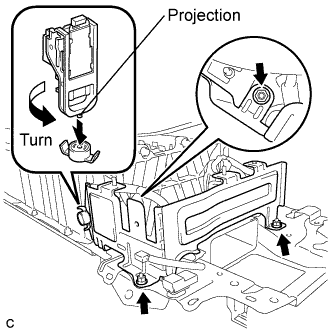
| 34. REMOVE BATTERY COOLING BLOWER ASSEMBLY |
 |
Disconnect the 3 wire harness clamps.
 |
Disconnect the battery cooling blower assembly connector and clamp.
Remove the 2 bolts, nut and battery cooling blower assembly.
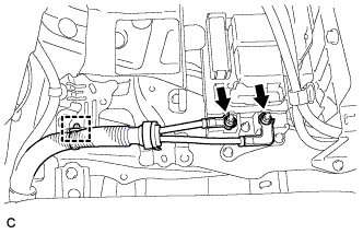
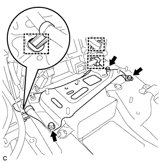
| 35. REMOVE NO. 7 HYBRID VEHICLE BATTERY UPPER CARRIER BRACKET |
 |
Disconnect the wire harness clamp.
Remove the bolt and No. 7 hybrid battery upper carrier bracket.
| 36. REMOVE CHILD RESTRAINT SEAT ANCHOR BRACKET SUB-ASSEMBLY LH |
 |
Remove the 2 bolts and child restraint seat anchor bracket sub-assembly LH.
| 37. REMOVE CHILD RESTRAINT SEAT ANCHOR BRACKET SUB-ASSEMBLY RH |
 |
Disconnect the wire harness protector clamp.
 |
Remove the 2 bolts and child restraint seat anchor bracket sub-assembly RH.
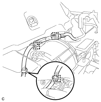
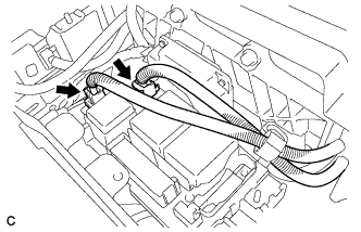
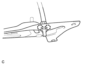
| 38. REMOVE FRAME WIRE |
 |
Remove the 2 nuts, then disconnect the frame wire from the hybrid battery junction block assembly.
Disconnect the clamp and frame wire.
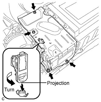
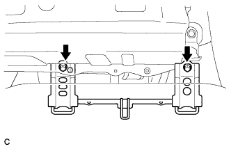
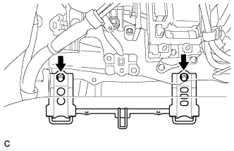
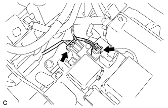
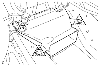
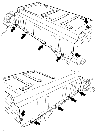
| 39. REMOVE HV BATTERY ASSEMBLY |
 |
Disconnect the connector and electrical key oscillator clamp.
 |
Remove the 4 bolts shown in the illustration.
Remove the HV battery.
| 40. REMOVE HYBRID BATTERY JUNCTION BLOCK |
 |
Disconnect the 2 connectors from the hybrid battery junction block.
 |
Disconnect the 2 connectors from the hybrid battery junction block.
 |
Remove the 3 nuts and hybrid battery junction block.
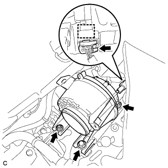
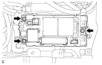
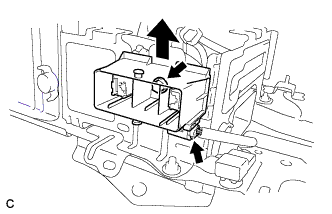
| 41. REMOVE BATTERY SMART UNIT |
 |
Disconnect the 3 connectors.
Remove the 2 nuts and battery smart unit.
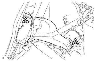
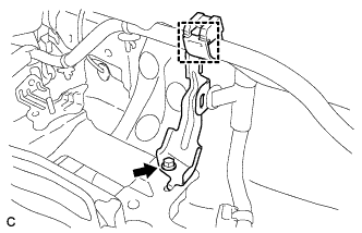
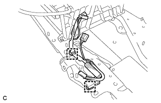
| 42. REMOVE NO. 1 HYBRID VEHICLE BATTERY CARRIER BRACKET SUB-ASSEMBLY |
 |
Disconnect the connector.
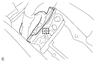
Remove the bolt and EV battery plug as shown in the illustration.
 |
Using the service plug grip, remove the battery cover lock striker.
Remove the 3 nuts and No. 1 hybrid vehicle battery carrier bracket sub-assembly.
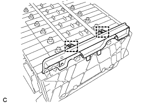
| 43. REMOVE NO. 4 HYBRID VEHICLE BATTERY CARRIER BRACKET SUB-ASSEMBLY |
 |
Disconnect the 3 wire harness clamps.
Remove the 3 bolts and No. 4 hybrid vehicle battery carrier bracket sub-assembly.
 |
Disengage the 2 claws and remove the HV battery thermistor.
| 44. REMOVE NO. 1 HYBRID BATTERY COVER INTAKE DUCT |
 |
Remove the 2 clips and No. 1 hybrid battery cover intake duct.
| 45. REMOVE UPPER HYBRID BATTERY COVER SUB-ASSEMBLY |
 |
Remove the 3 bolts, 8 nuts and battery cover with the No. 1 hybrid battery shield sub-assembly.
| 46. REMOVE NO. 1 HYBRID BATTERY PACKING |
 |
Remove the 2 clamps and No. 1 hybrid battery packing.
| 47. REMOVE NO. 2 HYBRID BATTERY PACK WIRE |
 |
Disconnect the 2 clamps, then remove the No. 2 hybrid battery pack wire.
