HV BATTERY > INSTALLATION |
| 1. INSTALL NO. 2 HYBRID BATTERY PACK WIRE |
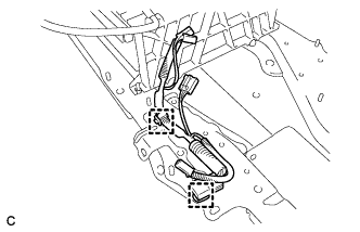 |
Connect the 2 clamps and No. 2 hybrid battery pack wire.
| 2. INSTALL NO. 1 HYBRID BATTERY PACKING |
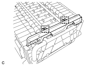 |
Install the No. 1 hybrid battery packing with the 2 clamps.
| 3. INSTALL UPPER HYBRID BATTERY COVER SUB-ASSEMBLY |
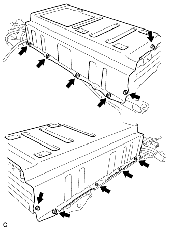 |
Install the battery cover and No. 1 hybrid battery shield sub-assembly with the 3 bolts and 8 nuts.
| 4. INSTALL NO. 1 HYBRID BATTERY COVER INTAKE DUCT |
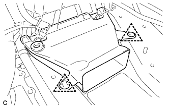 |
Install the No. 1 hybrid battery cover intake duct with the 2 clips.
| 5. INSTALL NO. 4 HYBRID VEHICLE BATTERY CARRIER BRACKET SUB-ASSEMBLY |
 |
Install the HV battery thermistor to the No. 4 hybrid vehicle battery carrier bracket sub-assembly.
 |
Install the No. 4 hybrid vehicle battery carrier bracket sub-assembly with the 3 bolts.
Connect the 3 wire harness clamps.
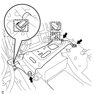
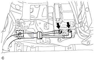
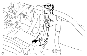
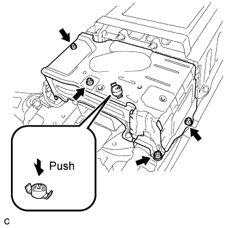
| 6. INSTALL NO. 1 HYBRID VEHICLE BATTERY CARRIER BRACKET SUB-ASSEMBLY |
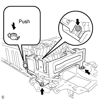 |
Install the No. 1 hybrid vehicle battery carrier bracket sub-assembly with the 3 nuts.
Install the battery cover lock striker, then push the button to lock it.
 |
Install the electric vehicle battery plug assembly with the bolt as shown in the illustration.
Connect the connector.
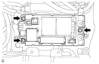
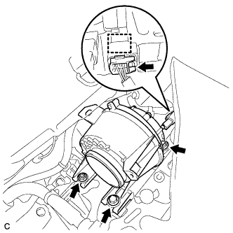
| 7. INSTALL BATTERY SMART UNIT |
 |
Install the battery smart unit with the 2 bolts.
Connect the 3 connectors.
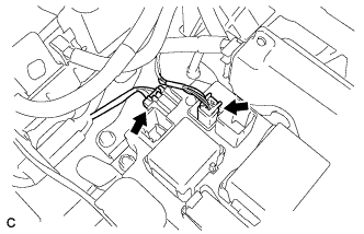
| 8. INSTALL HYBRID BATTERY JUNCTION BLOCK |
 |
Install the hybrid battery junction block with the 3 nuts.
 |
Connect the 2 connectors to the hybrid battery junction block.
 |
Connect the 2 connectors to the hybrid battery junction block.
| 9. INSTALL HV BATTERY ASSEMBLY |
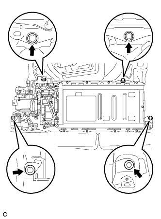 |
Install the HV battery to the vehicle with the 4 bolts.
 |
Connect the connector and electrical key oscillator clamp.
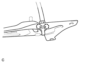
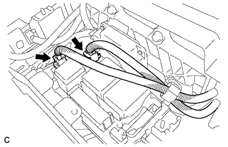
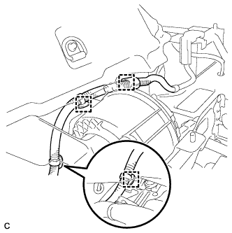
| 10. INSTALL FRAME WIRE |
 |
Install the frame wire on the hybrid battery junction block assembly with the 2 nuts.
Connect the clamp and frame wire.
| 11. CHECK HIGH VOLTAGE CABLE CONNECTION CONDITION |
Check that each wire harness is being installed securely.
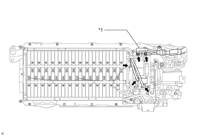
| *1 | Frame Wire | - | - |
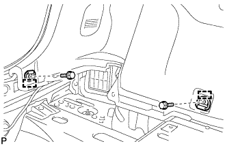
| 12. INSTALL CHILD RESTRAINT SEAT ANCHOR BRACKET SUB-ASSEMBLY LH |
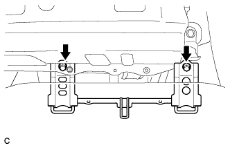 |
Install the child restraint seat anchor bracket sub-assembly LH with the 2 bolts.
| 13. INSTALL CHILD RESTRAINT SEAT ANCHOR BRACKET SUB-ASSEMBLY RH |
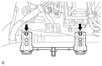 |
Install the child restraint seat anchor bracket sub-assembly RH with the 2 bolts.
 |
Connect the wire harness protector clamp.
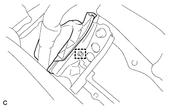
| 14. INSTALL NO. 7 HYBRID VEHICLE BATTERY UPPER CARRIER BRACKET |
 |
Install the No. 7 hybrid battery upper carrier bracket with the bolt.
| 15. INSTALL BATTERY COOLING BLOWER ASSEMBLY |
 |
Install the battery cooling blower assembly with the 2 bolts and nut
Connect each battery cooling blower assembly connector and clamp.
 |
Connect the 3 wire harness clamps.
| 16. INSTALL NO. 1 HYBRID BATTERY INTAKE DUCT |
 |
Install the No. 1 hybrid battery intake duct with the 2 clips.
| 17. INSTALL UPPER HYBRID BATTERY COVER SUB-ASSEMBLY |
 |
Install the upper hybrid battery cover sub-assembly with the 4 nuts.
Install the battery cover lock striker, then push the button to lock.
| 18. INSTALL NO. 1 HYBRID BATTERY EXHAUST DUCT |
 |
Insert the No. 1 hybrid battery exhaust duct with the clip.
| 19. INSTALL REAR FLOOR BOARD SPACER |
 |
Install the rear floor board spacer with the 2 clips.
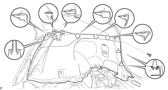
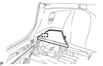
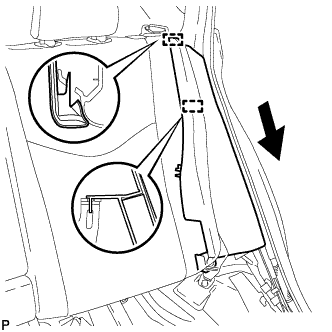
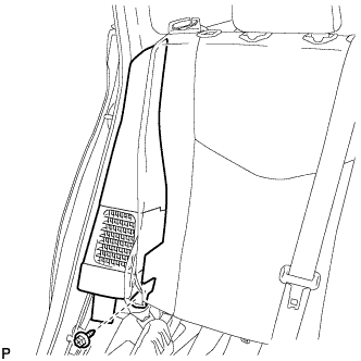
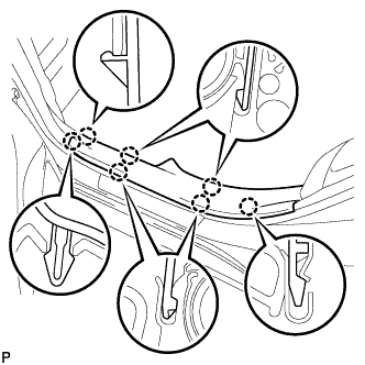
| 20. INSTALL DECK TRIM SIDE PANEL ASSEMBLY LH |
Connect the connector.
Engage the 7 claws and 2 clips.
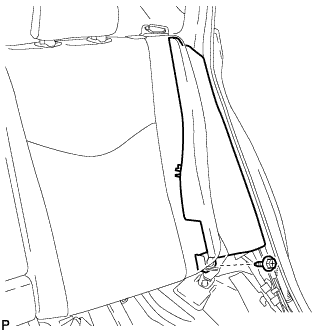
Install the deck trim side panel assembly LH with the screw.

| 21. INSTALL TONNEAU COVER HOLDER CAP (for LH Side) |
 |
Engage the claw to install the tonneau cover holder cap.
| 22. INSTALL LUGGAGE HOLD BELT STRIKER ASSEMBLY (for LH Side) |
 |
Engage the 2 guides.
Install the 2 luggage hold belt striker assemblies with the 2 bolts.
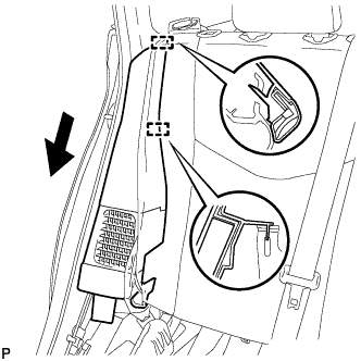
| 23. INSTALL DECK TRIM SIDE PANEL ASSEMBLY RH |
Engage the 7 claws and 2 clips.
Install the deck trim side panel assembly RH with the screw.
| 24. REMOVE TONNEAU COVER HOLDER CAP (for RH Side) |
| 25. INSTALL LUGGAGE HOLD BELT STRIKER ASSEMBLY (for RH Side) |
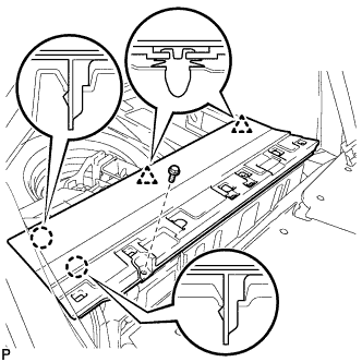
| 26. INSTALL REAR DECK TRIM COVER |
 |
Engage the 4 claws and 4 guides to install the rear deck trim cover.
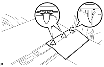
| 27. INSTALL DECK TRIM SERVICE HOLE COVER |
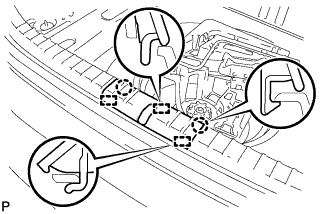 |
Engage the 3 guides.
Engage the 2 claws to install the deck trim service hole cover.
| 28. INSTALL DECK FLOOR BOX LH |
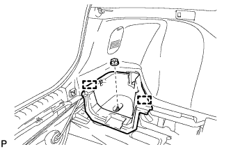 |
Engage the 2 guides.
Install the deck floor box LH with the clip.
| 29. INSTALL REAR NO. 4 FLOOR BOARD |
 |
Engage the guide to install the rear No. 4 floor board.
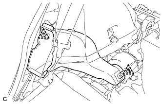
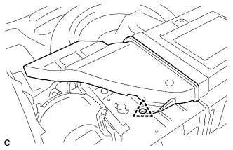
| 30. INSTALL REAR SIDE SEAT BACK ASSEMBLY LH |
 |
Engage the 2 guides as shown in the illustration.
 |
Install the rear side seatback assembly LH with the bolt.
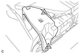
| 31. INSTALL REAR SIDE SEAT BACK ASSEMBLY RH |
 |
Engage the 2 guides as shown in the illustration.
 |
Install the rear side seatback assembly RH with the bolt.
| 32. INSTALL REAR DOOR SCUFF PLATE LH |
 |
Engage the 7 claws to install the rear door scuff plate LH.
| 33. INSTALL REAR DOOR SCUFF PLATE RH |
| 34. INSTALL REAR NO. 1 FLOOR BOARD |
 |
Engage the 2 claws and 2 clips.
Install the rear No. 1 floor board with the bolt.
| 35. INSTALL REAR NO. 2 FLOOR BOARD SUB-ASSEMBLY |
 |
Engage the claw and 2 clips to install the rear No. 2 floor board sub-assembly.
| 36. INSTALL REAR NO. 1 FLOOR BOARD SUB-ASSEMBLY |
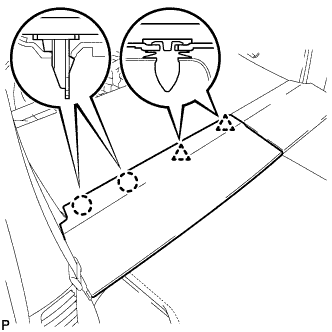 |
Engage the 2 claws and 2 clips to install the rear No. 1 floor board sub-assembly.
| 37. INSTALL REAR SEAT CUSHION ASSEMBLY |
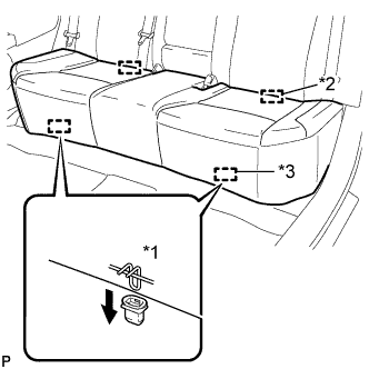 |
Engage the 2 guides of the seat cushion to the seatback.
| *1 | 100 mm (3.94 in.) or less |
| *2 | Guide |
| *3 | Hook |
Engage the 2 front hooks of the seat cushion to the vehicle body.
| 38. INSTALL TONNEAU COVER ASSEMBLY (w/ Tonneau Cover) |
Install the tonneau cover assembly.
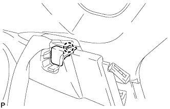
| 39. INSTALL SERVICE PLUG GRIP |
Wear insulated gloves and install the service plug grip in the order shown in the illustration.

Rotate the handle of the service plug grip 90° toward the battery and slide it in the direction shown by the arrow until a click sound is heard.
| 40. CONNECT CABLE TO NEGATIVE BATTERY TERMINAL |
| 41. INSTALL REAR NO. 3 FLOOR BOARD |
 |
Engage the 2 guides to install the rear No. 3 floor board.
| 42. INSTALL REAR DECK FLOOR BOX |
Install the rear deck floor box.
| 43. INSTALL REAR NO. 2 FLOOR BOARD |
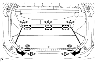 |
Engage the 3 guides <A>.
Engage the 2 guides <B> and install the rear No. 2 floor board as shown in the illustration.
