OUTER REAR VIEW MIRROR > REMOVAL |
| 1. PRECAUTION |
| 2. REMOVE REAR NO. 2 FLOOR BOARD |
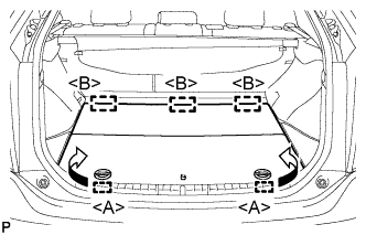 |
Disengage the 2 guides <A> as shown in the illustration.
Disengage the 3 guides <B> and remove the rear No. 2 floor board.
| 3. REMOVE REAR DECK FLOOR BOX |
Remove the rear deck floor box.
| 4. REMOVE REAR NO. 3 FLOOR BOARD |
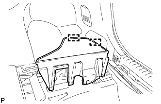 |
Disengage the 2 guides and remove the rear No. 3 floor board.
| 5. DISCONNECT CABLE FROM AUXILIARY BATTERY NEGATIVE TERMINAL |
| 6. REMOVE FRONT DOOR INSIDE HANDLE BEZEL PLUG |
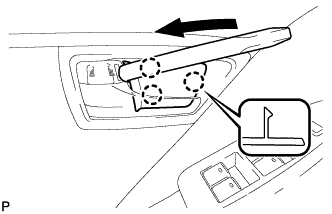 |
Using a moulding remover, disengage the 3 claws and remove the front door inside handle bezel plug.
| 7. REMOVE ASSIST GRIP COVER |
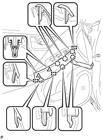 |
Using a moulding remover, disengage the 6 claws, 2 clips and 3 guides, and remove the assist grip cover.
| 8. REMOVE POWER WINDOW REGULATOR MASTER SWITCH ASSEMBLY WITH FRONT DOOR ARMREST BASE PANEL |
 |
Disengage the 7 claws and 3 guides.
Disconnect the connector and remove the power window regulator master switch assembly with front door armrest base panel.
| 9. REMOVE POWER WINDOW REGULATOR SWITCH ASSEMBLY WITH FRONT DOOR ARMREST BASE PANEL |
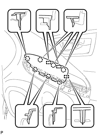 |
Disengage the 7 claws and 3 guides.
Disconnect the connector and remove the power window regulator switch assembly with front door armrest base panel.
| 10. REMOVE DOOR ARMREST COVER |
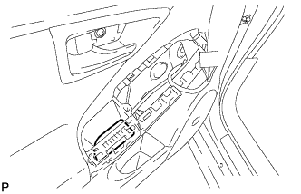 |
Remove the door armrest cover.
| 11. REMOVE COURTESY LIGHT ASSEMBLY |
 |
Using a moulding remover, disengage the claw.
Disconnect the connector and remove the courtesy light assembly.
| 12. REMOVE FRONT DOOR INSIDE HANDLE SUB-ASSEMBLY |
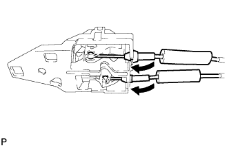 |
Disconnect the front door lock remote control cable and front door inside locking cable, and remove the front door inside handle sub-assembly.
| 13. REMOVE FRONT DOOR TRIM BOARD SUB-ASSEMBLY |
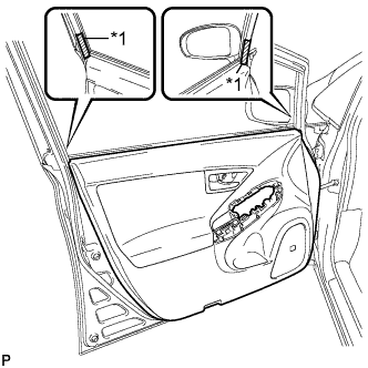 |
Put protective tape around the front door panel.
| *1 | Protective Tape |
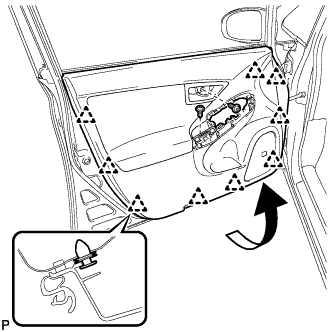 |
Remove the 2 screws.
Using a clip remover, disengage the 9 clips.
Pull out the front door trim board sub-assembly in the direction indicated by the arrow in the illustration.
Raise the front door trim board sub-assembly and remove the front door trim board sub-assembly together with the front door inner glass weatherstrip.
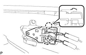 |
Disengage the 2 claws and disconnect the front door inside handle sub-assembly.
| 14. REMOVE OUTER MIRROR PROTECTOR |
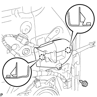 |
Remove the screw.
Disengage the 2 claws and remove the outer mirror protector.
| 15. REMOVE OUTER MIRROR INSTALL HOLE COVER |
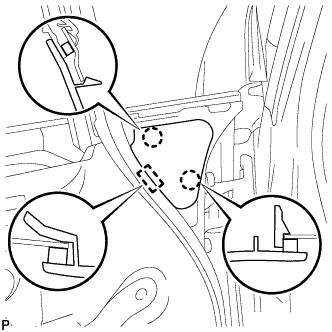 |
Disengage the 2 claws and guide, remove the outer mirror install hole cover.
| 16. REMOVE OUTER REAR VIEW MIRROR ASSEMBLY |
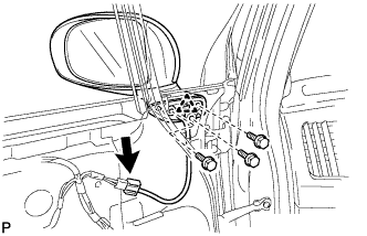 |
Disconnect the connector.
Remove the 3 bolts.
Disengage the clip and remove the outer rear view mirror assembly.
| 17. REMOVE OUTER MIRROR |
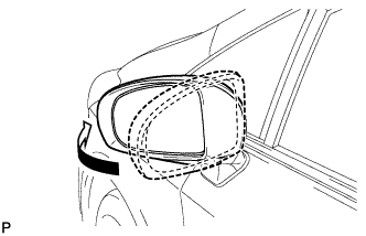 |
Push the outside part of the outer mirror assembly and tilt it as show in the illustration.
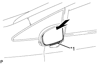 |
Push the upper part of the mirror surface and tilt it.
| *1 | Protruding Part |
Apply protective tape as shown in the illustration.
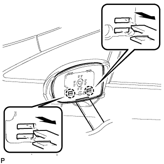 |
Using a moulding remover, disengage the 2 claws at the lower part of the outer rear view mirror, and separate the outer rear view mirror glass.
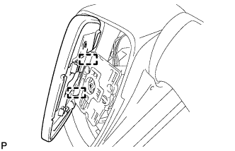 |
w/o Mirror Heater:
Disengage the 2 guides at the upper part of the outer mirror
Remove the outer mirror.
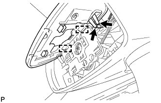 |
w/ Mirror Heater:
Disengage the 2 guides at the upper part of the outer mirror.
Disconnect the 2 connectors and remove the outer mirror.
| 18. REMOVE OUTER MIRROR COVER |
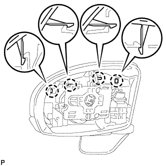 |
Disengage the 4 claws.
 |
Disengage the 3 claws and remove the outer mirror cover as shown in the illustration.