MILLIMETER WAVE RADAR SENSOR > INSTALLATION |
| 1. INSTALL MILLIMETER WAVE RADAR SENSOR ASSEMBLY |
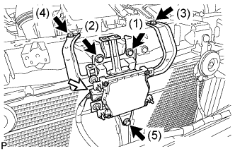 |
Tighten the 5 bolts on the millimeter wave radar sensor assembly.
Connect the connector.
| 2. INSTALL FRONT BUMPER ASSEMBLY |
Connect the headlight cleaner hose. (w/ Headlight Cleaner System)
Connect each connector.
 |
Install the front bumper assembly as shown in the illustration.
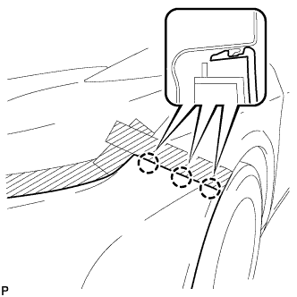 |
Engage the 3 claws to install the front bumper assembly.
 |
Engage the 2 guides and install the front spoiler cover. (w/ Front Spoiler)
Install the 2 clips and 2 screws. (w/ Front Spoiler)
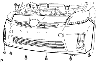 |
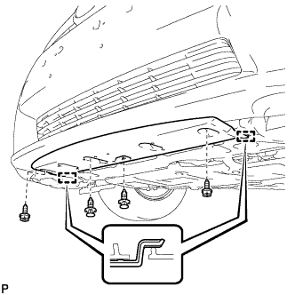
Install the 7 clips.
Install the 2 bolts and 4 screws.
 |
Install the screw.
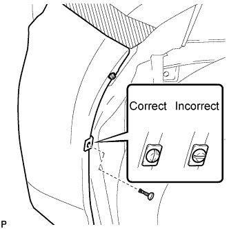 |
Install the pin hold clip.
| 3. ADD WASHER FLUID (w/ Headlight Cleaner System) |
| 4. PREPARE VEHICLE FOR FOG LIGHT AIMING ADJUSTMENT |
Prepare the vehicle:
| 5. PREPARE FOR FOG LIGHT AIMING |
 |
Prepare the vehicle (except Taiwan):
 |
Prepare the vehicle (for Taiwan):
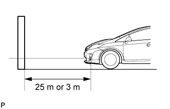
Prepare a piece of thick white paper (approximately 2 m (6.6 ft.) (height) x 4 m (13.1 ft.) (width)) to use as a screen.
Draw a vertical line down the center of the screen (V line).
Set the screen as shown in the illustration (except Taiwan).
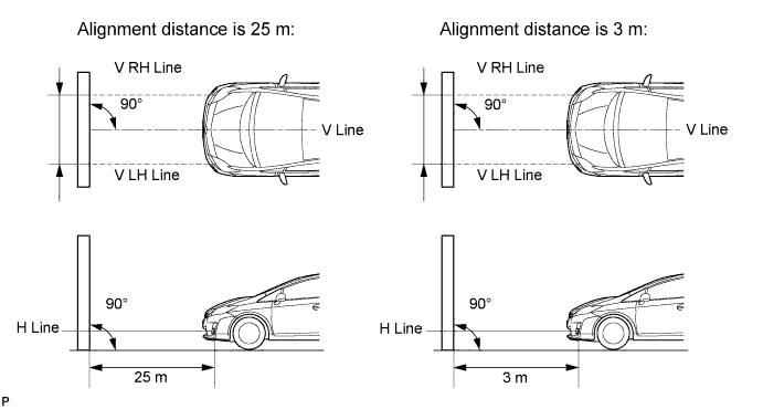
Set the screen as shown in the illustration (for Taiwan).

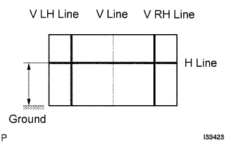 |
Draw base lines (H, V LH, and V RH lines) on the screen as shown in the illustration.
H Line (Fog light height):
Draw a horizontal line across the screen so that it passes through the center marks. The H line should be at the same height as the fog light bulb center marks of the fog lights.
V LH Line, V RH Line (Center mark position of left-hand (LH) and right-hand (RH) fog lights):
Draw two vertical lines so that they intersect the H line at each center mark (aligned with the center of the fog light bulbs).
| 6. INSPECT FOG LIGHT AIMING |
Cover the fog light or disconnect the connector of the fog light on the opposite side to prevent light from the fog light that is not being inspected from affecting the fog light aiming inspection.
Start the engine.
Turn on the fog lights and check if the upper edge of the hot zone for each fog light matches the upper edge as shown in the illustration (except Taiwan).
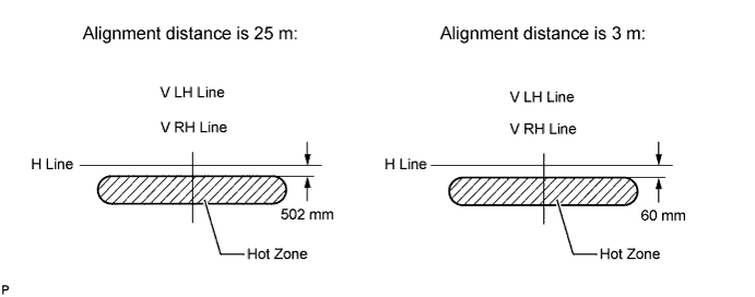
Turn on the fog lights and check if the upper edge of the hot zone for each fog light matches the upper edge as shown in the illustration (for Taiwan).

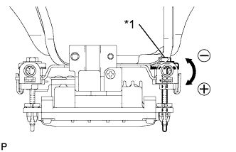
| 7. ADJUST FOG LIGHT AIMING |
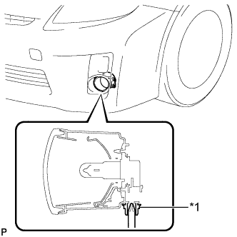 |
Adjust the aim vertically:
Adjust the aim of each fog light to the specified range by turning each aiming screw with a screwdriver.
| *1 | Aiming Screw |
| 8. ADJUST MILLIMETER WAVE RADAR SENSOR ASSEMBLY |
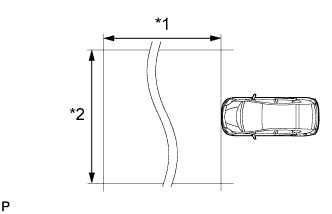 |
| *1 | Approx. 10 m |
| *2 | Approx. 14 m |
Before adjusting the radar beam axis, prepare the vehicle as follows.
Check the tire pressure and adjust it if necessary.
Remove all excess weight from the vehicle (luggage, heavy objects, etc.).
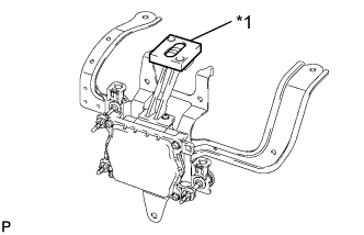 |
Check and adjust the vertical direction of the radar sensor.
| *1 | Level |
Remove dust, oil and foreign matter from the radar sensor's level rack.
Set a level on the radar sensor's level rack.
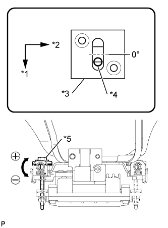 |
Check that the level's air bubble is within the red frame.
| *1 | FR |
| *2 | LH |
| *3 | Level |
| *4 | Air Bubble |
| *5 | Bolt A |
| Adjustment Direction | Adjustment Procedure | Adjustment Angle |
| Vertical adjustment | Upward direction: Turn bolt A to negative (-) side | For every 1.4 rotations of adjustment bolt, sensor moves about 1° |
| Downward direction: Turn bolt A to positive (+) side |
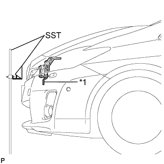 |
Adjust the reflector height.
| *1 | Millimeter Wave Radar Sensor |
Adjust the reflector so that the center of SST reflector is the same height as the millimeter wave radar sensor.
 |
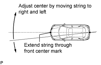
Place the reflector.
Hang the string (with weight) from the center of the vehicle's rear emblem. Mark the vehicle's rear center point on the ground. Repeat for the front of the vehicle.
 |
Set one end of the 10 m (32.8 ft.) string on the vehicle's rear center point. Run the string over the vehicle's front center point to a position 5 m (16.4 ft.) beyond the vehicle's front center point, as shown in the illustration. Mark the 5 m (16.4 ft.) position.
Using a tape measure, measure 15.7 mm (0.618 in.) to the right of the 5 m (16.4 ft.) position. Place the reflector at that position.
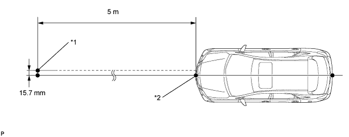
| *1 | Reflector Placement Point | *2 | Millimeter Wave Radar Sensor Position |
Check the radar beam axis.
When using the intelligent tester:
Connect the intelligent tester to the DLC3.
Turn the power switch on (IG).
Turn the intelligent tester on, and turn the cruise control main switch on.
Select "Auto" from the intelligent tester display screen.
Select "Radar Cruise" from the display screen.
Select "Utility" from the display screen.
Select "Beam Axis Adjustment" from the display screen.
Follow the tester display, and select "Next".
Check the following items on the laser cruise divergence data screen.
Check and adjust the horizontal direction of the radar sensor.
Check that the divergence of the radar beam axis is 0°.
 |
Based on the measured divergence of the beam axis, turn and adjust the bolt B for horizontal adjustment of the millimeter wave radar sensor using a screwdriver.
| *1 | Bolt B |
| Adjustment Direction | Adjustment Procedure | Adjustment Angle |
| Horizontal adjustment | Right direction: Turn bolt B to positive (+) side. | For every 2.5 rotations of adjustment bolt, sensor moves about 1° |
| Left direction: Turn bolt B to negative (-) side. |
Select "Next". The driving learning value is automatically reset.
Disconnect the intelligent tester from the DLC3.
Recheck and readjust the vertical direction of the radar sensor.
|
Set a level on the radar sensor's level rack.
| *1 | Level |
|
Check that the level's air bubble is within the red frame.
| *1 | FR |
| *2 | LH |
| *3 | Level |
| *4 | Air Bubble |
| *5 | Bolt A |
| Adjustment Direction | Adjustment Procedure | Adjustment Angle |
| Vertical adjustment | Upward direction: Turn bolt A to negative (-) side | For every 1.4 rotations of adjustment bolt, sensor moves about 1° |
| Downward direction: Turn bolt A to positive (+) side |
| 9. INSTALL RADIATOR SUPPORT OPENING COVER |
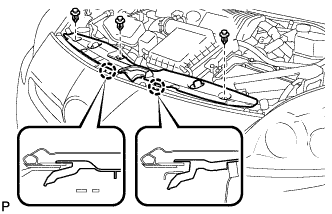 |
Engage the 2 claws and install the radiator support opening cover.
Install the 3 clips.
