DTC C1380/64 Stop Light Control Relay Malfunction |
| DTC Code | INF Code | DTC Detection Condition | Trouble Area |
| C1380/64 | 761 | When the voltage at the IG1 terminal is 9.5 V or more and the stop light control relay drive output (STP0) is ON, a signal is not input to the STP2 and EXO terminal for 2 seconds or more. |
|
| ↑ | 762 | When the voltage at the IG1 terminal is 9.5 V or more and the stop light control relay drive output (STP0) is OFF, the signal at the STP terminal is different from the input signal at the STP2 and EXO for 5 seconds or more. |
|
| 1.CHECK STOP LIGHT OPERATION |
Check that the stop lights come on when the brake pedal is depressed and go off when the brake pedal is released.
| Condition | Illumination Condition |
| Brake pedal depressed | ON |
| Brake pedal released | OFF |
|
| ||||
| OK | |
| 2.READ VALUE USING INTELLIGENT TESTER (STOP LIGHT SWITCH) |
Connect the intelligent tester to the DLC3.
Turn the power switch on (IG).
Select the Data List on the intelligent tester (Click here).
| Tester Display | Measurement Item/Range | Normal Condition | Diagnostic Note |
| Stop Light SW | Stop light switch / ON or OFF | ON: Brake pedal depressed OFF: Brake pedal released | - |
Check that the stop light switch condition observed on the intelligent tester changes according to brake pedal operation.
|
| ||||
| OK | |
| 3.PERFORM ACTIVE TEST USING INTELLIGENT TESTER (STOP LIGHT CONTROL RELAY) |
Select the Active Test on the intelligent tester (Click here).
| Tester Display | Test Part | Control Range | Diagnostic Note |
| Stop Light Relay | Stop light control relay | Relay ON/OFF | Stop lights come on |
| EBS Relay*1 | Stop light control relay (Emergency brake signal) | Relay ON/OFF |
|
Perform the Active Test of the stop light control relay using the intelligent tester.
Select the Data List on the intelligent tester (Click here).
| Tester Display | Measurement Item/Range | Normal Condition | Diagnostic Note |
| Stop Light Relay Output | Stop light control relay output / ON or OFF | ON: Relay output on OFF: Relay output off | - |
| EBS Relay*1 | Stop light control relay (Emergency brake signal) / ON or OFF | ON: Relay on OFF: Relay off |
|
Check for stop light control relay operation using Data List and stop light operation by performing an Active Test.
| Result | Proceed to |
| Data List content and stop light operation are normal | A |
| Data List content is normal but stop lights do not turn on or off | B |
|
| ||||
| A | |
| 4.INSPECT SKID CONTROL ECU (STP2 TERMINAL) |
 |
Turn the power switch off.
Make sure that there is no looseness at the locking part and the connecting part of the connectors.
Disconnect the skid control ECU connector.
Measure the voltage according to the value(s) in the table below.
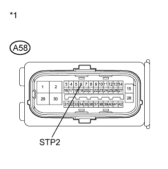
| Tester Connection | Switch Condition | Specified Condition |
| A58-6 (STP2) - Body ground | Stop light switch ON (Brake pedal depressed) | 11 to 14 V |
| A58-6 (STP2) - Body ground | Stop light switch OFF (Brake pedal released) | Below 1.5 V |
| *1 | Front view of wire harness connector (to Skid Control ECU) |
|
| ||||
| OK | |
| 5.RECONFIRM DTC |
Reconnect the skid control ECU connector.
Clear the DTCs (Click here).
Turn the power switch on (READY).
Perform a road test.
Check if the same DTC is recorded (Click here).
| Result | Proceed to |
| DTC (C1380/64) is not output | A |
| DTC (C1380/64) is output (for LHD) | B |
| DTC (C1380/64) is output (for RHD) | C |
|
| ||||
|
| ||||
| A | ||
| ||
| 6.INSPECT STOP LIGHT CONTROL RELAY |
Inspect the stop light control relay (Click here).
|
| ||||
| OK | |
| 7.CHECK HARNESS AND CONNECTOR (SKID CONTROL ECU - STOP LIGHT CONTROL RELAY) |
 |
Make sure that there is no looseness at the locking part and the connecting part of the connectors.
Disconnect the skid control ECU connector and the stop light control relay connector.
Measure the resistance according to the value(s) in the table below.
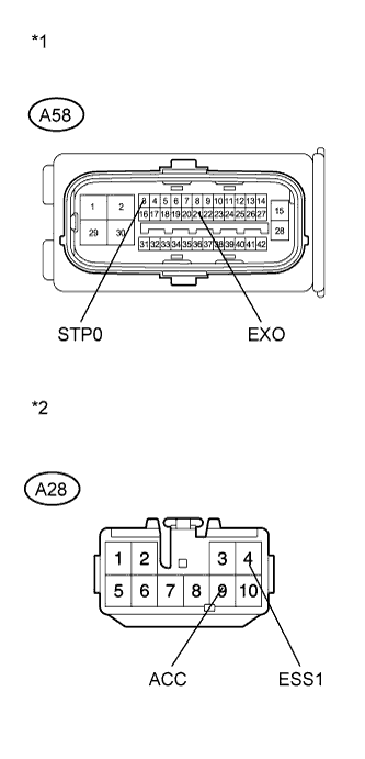
| Tester Connection | Condition | Specified Condition |
| A58-3 (STP0) - A28-9 (ACC) | Always | Below 1 Ω |
| A58-3 (STP0) - Body ground | Always | 10 kΩ or higher |
| A58-21 (EXO)*1 - A28-4 (ESS1)*1 | Always | Below 1 Ω |
| A58-21 (EXO)*1 - Body ground | Always | 10 kΩ or higher |
| *1 | Front view of wire harness connector (to Skid Control ECU) |
| *2 | Front view of wire harness connector (to Stop Light Control Relay) |
| Result | Proceed to |
| OK (for LHD) | A |
| OK (for RHD) | B |
| NG | C |
|
| ||||
|
| ||||
| A | ||
| ||
| 8.INSPECT SKID CONTROL ECU (STP TERMINAL) |
 |
Turn the power switch off.
Make sure that there is no looseness at the locking part and the connecting part of the connector.
Disconnect the skid control ECU connector.
Measure the voltage according to the value(s) in the table below.
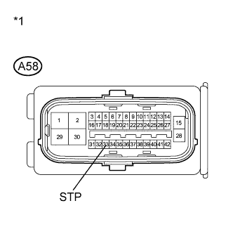
| Tester Connection | Switch Condition | Specified Condition |
| A58-33 (STP) - Body ground | Stop light switch ON (Brake pedal depressed) | 11 to 14 V |
| A58-33 (STP) - Body ground | Stop light switch OFF (Brake pedal released) | Below 1.5 V |
| *1 | Front view of wire harness connector (to Skid Control ECU) |
| Result | Proceed to |
| OK (for LHD) | A |
| OK (for RHD) | B |
| NG | C |
|
| ||||
|
| ||||
| A | ||
| ||
