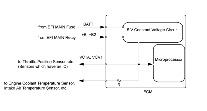
SFI SYSTEM (w/ EGR System) > VC Output Circuit |
| 1.CHECK MIL |
Check that the Malfunction Indicator Lamp (MIL) illuminates when turning the power switch on (IG).
|
| ||||
| OK | ||
| ||
| 2.CHECK CONNECTION BETWEEN INTELLIGENT TESTER AND ECM |
Connect the intelligent tester to the DLC3.
Turn the power switch on (IG).
Turn the tester on.
Check the communication between the intelligent tester and ECM.
| Result | Proceed to |
| Communication is possible | A |
| Communication is not possible | B |
|
| ||||
| B | |
| 3.CHECK MIL (THROTTLE POSITION SENSOR) |
Disconnect the throttle position sensor connector.
Turn the power switch on (IG).
Check the MIL.
| Result | Proceed to |
| MIL illuminates | A |
| MIL does not illuminate | B |
Reconnect the throttle position sensor connector.
|
| ||||
| B | |
| 4.CHECK MIL (CAMSHAFT POSITION SENSOR) |
Disconnect the camshaft position sensor connector.
Turn the power switch on (IG).
Check the MIL.
| Result | Proceed to |
| MIL illuminates | A |
| MIL does not illuminate | B |
Reconnect the camshaft position sensor connector.
|
| ||||
| B | |
| 5.CHECK MIL (MANIFOLD ABSOLUTE PRESSURE SENSOR) |
Disconnect the manifold absolute pressure sensor connector.
Turn the power switch on (IG).
Check the MIL.
| Result | Proceed to |
| MIL illuminates | A |
| MIL does not illuminate | B |
Reconnect the manifold absolute pressure sensor connector.
|
| ||||
| B | |
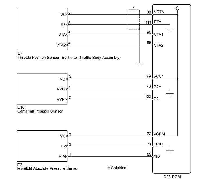
| 6.CHECK HARNESS AND CONNECTOR (THROTTLE POSITION SENSOR - ECM) |
Disconnect the throttle position sensor connector.
Disconnect the ECM connector.
Measure the resistance according to the value(s) in the table below.
| Tester Connection | Condition | Specified Condition |
| D28-88 (VCTA) or D4-5 (VC) - Body ground | Always | 10 kΩ or higher |
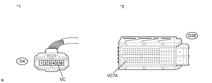
| *1 | Front view of wire harness connector (to Throttle Position Sensor) | *2 | Front view of wire harness connector (to ECM) |
Reconnect the throttle position sensor connector.
Reconnect the ECM connector.
|
| ||||
| OK | |
| 7.CHECK HARNESS AND CONNECTOR (CAMSHAFT POSITION SENSOR - ECM) |
Disconnect the camshaft position sensor connector.
Disconnect the ECM connector.
Measure the resistance according to the value(s) in the table below.
| Tester Connection | Condition | Specified Condition |
| D18-3 (VC) or D28-99 (VCV1) - Body ground | Always | 10 kΩ or higher |
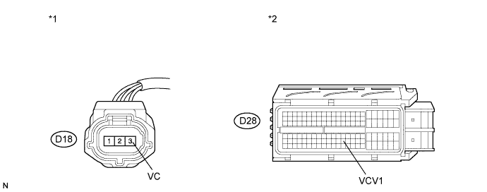
| *1 | Front view of wire harness connector (to Camshaft Position Sensor) | *2 | Front view of wire harness connector (to ECM) |
Reconnect the camshaft position sensor connector.
Reconnect the ECM connector.
|
| ||||
| OK | |
| 8.CHECK HARNESS AND CONNECTOR (MANIFOLD ABSOLUTE PRESSURE SENSOR - ECM) |
Disconnect the manifold absolute pressure sensor connector.
Disconnect the ECM connector.
Measure the resistance according to the value(s) in the table below.

| Tester Connection | Condition | Specified Condition |
| D3-3 (VC) or D28-72 (VCPM) - Body ground | Always | 10 kΩ or higher |
| *1 | Front view of wire harness connector (to Manifold Absolute Pressure Sensor) | *2 | Front view of wire harness connector (to ECM) |
Reconnect the manifold absolute pressure sensor connector.
Reconnect the ECM connector.
|
| ||||
| OK | ||
| ||
