POWER DOOR LOCK CONTROL SYSTEM > TERMINALS OF ECU |
| CHECK INSTRUMENT PANEL JUNCTION BLOCK ASSEMBLY AND MAIN BODY ECU (MULTIPLEX NETWORK BODY ECU) |
Disconnect the 2B and 2C junction block connectors.
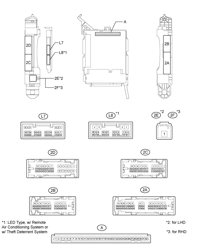
Disconnect the A main body ECU connector.
Measure the voltage and resistance according to the value(s) in the table below.
| Tester Connection | Wiring Color | Terminal Description | Condition | Specified Condition |
| 2B-6 (GND1) - Body ground | W-B - Body ground | Ground | Always | Below 1 Ω |
| 2C-18 (BECU) - Body ground | Y - Body ground | Battery power supply | Power switch off | 11 to 14 V |
| A-29 (ACC) - Body ground | - | ACC power supply | Power switch on (ACC) | 11 to 14 V |
| A-29 (ACC) - Body ground | - | ACC power supply | Power switch off | Below 1 V |
| A-31 (ALTB) - Body ground | - | Battery power supply | Power switch off | 11 to 14 V |
| A-32 (IG) - Body ground | - | Power switch power supply | Power switch on (IG) | 11 to 14 V |
| A-32 (IG) - Body ground | - | Power switch power supply | Power switch off | Below 1 V |
Reconnect the 2B and 2C junction block connectors.
Reconnect the A main body ECU connector.
Measure the voltage according to the value(s) in the table below.
| Tester Connection | Wiring Color | Terminal Description | Condition | Specified Condition |
| 2B-1 (ACT-) - Body ground | B - Body ground | Door lock motor unlock drive output (all doors) | Driver side door control switch off | Below 1 V |
| 2B-1 (ACT-) - Body ground | B - Body ground | Door lock motor unlock drive output (all doors) | Driver side door control switch unlocked | 11 to 14 V |
| 2B-8 (ACT+) - Body ground | L - Body ground | Door lock motor lock drive output (all doors) | Driver side door control switch off | Below 1 V |
| 2B-8 (ACT+) - Body ground | L - Body ground | Door lock motor lock drive output (all doors) | Driver side door control switch locked | 11 to 14 V |
| 2D-36 (FRCY) - Body ground | BR - Body ground | Front door courtesy switch RH input | Front door RH open | Below 1 V |
| 2D-36 (FRCY) - Body ground | BR - Body ground | Front door courtesy switch RH input | Front door RH closed | 11 to 14 V |
| 2D-35 (FLCY) - Body ground | V - Body ground | Front door courtesy switch LH input | Front door LH open | Below 1 V |
| 2D-35 (FLCY) - Body ground | V - Body ground | Front door courtesy switch LH input | Front door LH closed | 11 to 14 V |
| 2D-25 (LSR) - Body ground | GR - Body ground | Rear door LH lock position switch input | Rear door LH unlocked | Below 1 V |
| 2D-25 (LSR) - Body ground | GR - Body ground | Rear door LH lock position switch input | Power switch off, all doors closed and rear door LH locked | 11 to 14 V |
| 2B-29 (LSR) - Body ground | GR - Body ground | Rear door RH lock position switch input | Rear door RH unlocked | Below 1 V |
| 2B-29 (LSR) - Body ground | GR - Body ground | Rear door RH lock position switch input | Power switch off, all doors closed and rear door RH locked | 11 to 14 V |
| L7-6 (LRCY) - Body ground | G - Body ground | Rear door courtesy light switch input | Rear left side door or rear right side door open | Below 1 V |
| L7-6 (LRCY) - Body ground | G - Body ground | Rear door courtesy light switch input | Rear left side door and rear right side door closed | 11 to 14 V |
| L7-7 (LSFL) - Body ground | GR - Body ground | Front door LH lock position switch input | Front door LH unlocked | Below 1 V |
| L7-7 (LSFL) - Body ground | GR - Body ground | Front door LH lock position switch input | Power switch off, all doors closed and front door LH locked | 11 to 14 V |
| L7-11 (L2) - Body ground | G - Body ground | Driver door key-linked lock input | Driver door key cylinder turned to lock | Below 1 V |
| L7-11 (L2) - Body ground | G - Body ground | Driver door key-linked lock input | Driver door key cylinder off | 11 to 14 V |
| L7-18 (LSFR) - Body ground | LG - Body ground | Front door RH lock position switch input | Front door RH unlocked | Below 1 V |
| L7-18 (LSFR) - Body ground | LG - Body ground | Front door RH lock position switch input | Power switch off, all doors closed and front door RH locked | 11 to 14 V |
| L7-19 (BCTY) - Body ground | L - Body ground | Back door courtesy light switch input | Back door open | Below 1 V |
| L7-19 (BCTY) - Body ground | L - Body ground | Back door courtesy light switch input | Back door closed | 11 to 14 V |
| L7-23 (BDSU) - Body ground*1 | GR - Body ground | Back door opener switch input | Back door opener switch pushed | Below 1 V |
| L7-23 (BDSU) - Body ground*1 | GR - Body ground | Back door opener switch input | Back door opener switch not pushed | 11 to 14 V |
| L7-12 (UL2) - Body ground | V - Body ground | Driver door key-linked unlock input | Driver door key cylinder turned to unlock | Below 1 V |
| L7-12 (UL2) - Body ground | V - Body ground | Driver door key-linked unlock input | Driver door key cylinder off | 11 to 14 V |
| CHECK CERTIFICATION ECU (SMART KEY ECU ASSEMBLY) (w/ Entry System Back Door Open Function) |
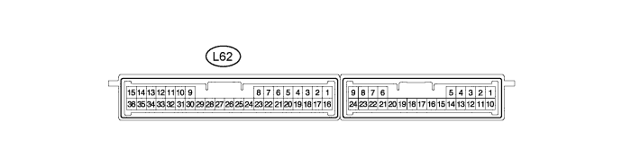
Disconnect the L62 certification ECU (smart key ECU assembly) connector.
Measure the resistance according to the value(s) in the table below.
| Tester Connection | Wiring Color | Terminal Description | Condition | Specified Condition |
| L62-22 (TSW5) - Body ground | GR - Body ground | Back door opener switch signal | Back door opener switch on | Below 1 Ω |
| L62-22 (TSW5) - Body ground | GR - Body ground | Back door opener switch signal | Back door opener switch off | 10 kΩ or higher |
Reconnect the L62 certification ECU (smart key ECU assembly) connector.
Measure the voltage according to the value(s) in the table below.
| Tester Connection | Wiring Color | Terminal Description | Condition | Specified Condition |
| L62-22 (TSW5) - Body ground | GR - Body ground | Back door opener switch signal | Back door opener switch off | 11 to 14 V |
| L62-22 (TSW5) - Body ground | GR - Body ground | Back door opener switch signal | Back door opener switch on | Below 1 V |
| CHECK DOUBLE LOCK DOOR CONTROL RELAY ASSEMBLY (w/ Double Locking System) |
Disconnect the L105 double lock door control relay assembly connector.

Measure the voltage and resistance according to the value(s) in the table below.
| Tester Connection | Wiring Color | Terminal Description | Condition | Specified Condition |
| L105-1 (+B) - Body ground | R - Body ground | Battery power supply | Always | 11 to 14 V |
| L105-7 (CPUB) - Body ground | Y - Body ground | Battery power supply | Always | 11 to 14 V |
| L105-14 (GND) - Body ground | W-B - Body ground | Ground | Always | Below 1 Ω |
Reconnect the L105 double lock door control relay assembly connector.
Measure the voltage according to the value(s) in the table below.
| Tester Connection | Wiring Color | Terminal Description | Condition | Specified Condition |
| L105-5 (DLPD) - Body ground | Y - Body ground | Front RH double lock position switch input | Double lock unset | Pulse generation |
| L105-5 (DLPD) - Body ground | Y - Body ground | Front RH double lock position switch input | Double lock set | Below 1 V |
| L105-6 (DLPP) - Body ground | V - Body ground | Front LH double lock position switch input | Double lock unset | Pulse generation |
| L105-6 (DLPP) - Body ground | V - Body ground | Front LH double lock position switch input | Double lock set | Below 1 V |
| L105-11 (DLPR) - Body ground | G - Body ground | Rear RH double lock position switch input | Double lock unset | Pulse generation |
| L105-11 (DLPR) - Body ground | G - Body ground | Rear RH double lock position switch input | Double lock set | Below 1 V |
| L105-12 (DLPL) - Body ground | L - Body ground | Rear LH double lock position switch input | Double lock unset | Pulse generation |
| L105-12 (DLPL) - Body ground | L - Body ground | Rear LH double lock position switch input | Double lock set | Below 1 V |
| L105-3 (ACTS) - Body ground | LG - Body ground | All door double lock motor set on output | Double lock unset | Below 1 V |
| L105-3 (ACTS) - Body ground | LG - Body ground | All door double lock motor set on output | Double lock set | 11 to 14 V |
| L105-4 (ACTR) - Body ground | GR - Body ground | All door double lock motor set off output | Double lock set | Below 1 V |
| L105-4 (ACTR) - Body ground | GR - Body ground | All door double lock motor set off output | Double lock unset | 11 to 14 V |
