FRONT AXLE HUB > REMOVAL |
| 1. PRECAUTION (w/ Navigation System for HDD) |
| 2. REMOVE REAR NO. 2 FLOOR BOARD |
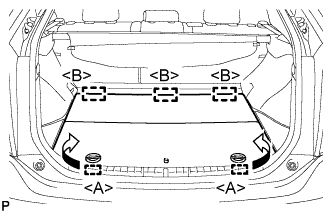 |
Disengage the 2 guides <A> as shown in the illustration.
Disengage the 3 guides <B> and remove the rear No. 2 floor board.
| 3. REMOVE REAR DECK FLOOR BOX |
Remove the rear deck floor box.
| 4. REMOVE REAR NO. 3 FLOOR BOARD |
 |
Disengage the 2 guides and remove the rear No. 3 floor board.
| 5. DISABLE BRAKE CONTROL |
Wait at least 2 minutes after the power switch off.
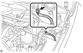 |
Disconnect the reservoir level switch connector with the parking brake applied.
Disconnect the cable from the negative (-) battery terminal.
Depress the brake pedal 40 times or more to return all the fluid in the accumulator back to the reservoir.
Check that the brake pedal can not be further depressed.
Release the parking brake.
| 6. REMOVE FRONT WHEEL |
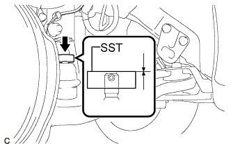
| 7. REMOVE FRONT AXLE SHAFT NUT |
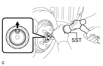 |
Using SST and a hammer, release the staked part of the front axle shaft nut.
While applying the brakes, remove the front axle shaft nut.
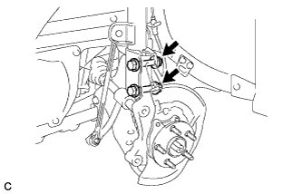
| 8. SEPARATE FRONT SPEED SENSOR |
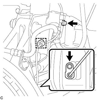 |
Remove the 2 bolts and clamp, and separate the front speed sensor.
| 9. SEPARATE FRONT FLEXIBLE HOSE |
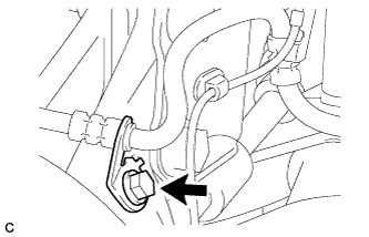 |
Remove the bolt and separate the front flexible hose from the steering knuckle.
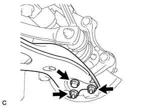
| 10. SEPARATE FRONT DISC BRAKE CALIPER ASSEMBLY |
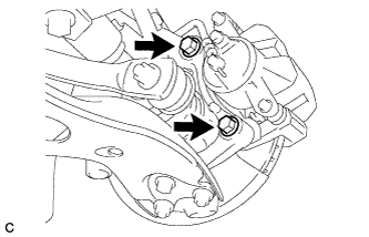 |
Remove the 2 bolts and separate the front disc brake caliper assembly.
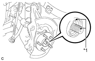
| 11. REMOVE FRONT DISC |
 |
Remove the front disc.
| *1 | Matchmark |
| 12. SEPARATE TIE ROD END SUB-ASSEMBLY |
Remove the clip and nut.
 |
Install SST to the tie rod end.
Using SST, separate the tie rod end from the steering knuckle.
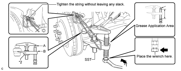
| *1 | Turn | *2 | Nut |
| 13. SEPARATE FRONT NO. 1 LOWER SUSPENSION ARM SUB-ASSEMBLY |
 |
Remove the bolt and 2 nuts, and separate the front No. 1 lower suspension arm sub-assembly from the front lower ball joint.
| 14. SEPARATE FRONT DRIVE SHAFT ASSEMBLY |
 |
Put matchmarks on the front drive shaft assembly and front axle hub sub-assembly.
| *1 | Matchmark |
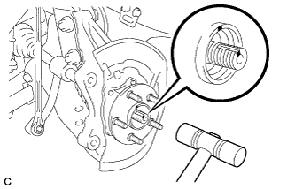 |
Using a plastic hammer, separate the front drive shaft assembly from the front axle assembly. If it is difficult to separate, tap the end of the front drive shaft assembly using a brass bar and a hammer.
| 15. REMOVE FRONT AXLE ASSEMBLY |
 |
Remove the 2 bolts, 2 nuts and front axle assembly.
| 16. REMOVE FRONT AXLE HUB SUB-ASSEMBLY |
Secure the front axle assembly between aluminium plates in a vise.
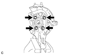 |
Remove the 4 bolts, front axle hub sub-assembly and front disc brake dust cover.
