Home

Toyota Workshop

GSIC - Global Service Information Center

FUEL INJECTOR > REMOVAL

for Preparation Click here


1. PRECAUTION (w/ Navigation System for HDD)

NOTICE:
After the power switch is turned off, the navigation receiver assembly (HDD navigation system) records various types of memory and settings. As a result, after turning the power switch off, make sure to wait at least 60 seconds before disconnecting the cable from the negative (-) battery terminal.


2. DISCHARGE FUEL SYSTEM PRESSURE
  1. Discharge fuel system pressure (Click here).


3. REMOVE REAR NO. 2 FLOOR BOARD


    B227787E01
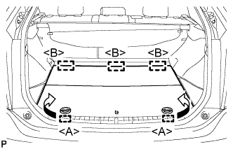
  1. Disengage the 2 guides <A> as shown in the illustration.

  1. Disengage the 3 guides <B> and remove the rear No. 2 floor board.


4. REMOVE REAR DECK FLOOR BOX
  1. Remove the rear deck floor box.


5. REMOVE REAR NO. 3 FLOOR BOARD


    B227791
  1. Disengage the 2 guides and remove the rear No. 3 floor board.


6. DISCONNECT CABLE FROM NEGATIVE BATTERY TERMINAL

NOTICE:
When disconnecting the cable, some systems need to be initialized after the cable is reconnected (Click here).


7. REMOVE EGR WITH COOLER PIPE SUB-ASSEMBLY

HINT:
Click here.


8. DISCONNECT ENGINE WIRE


A216398
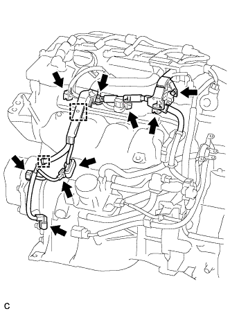
  1. Disconnect the 4 fuel injector connectors.

  1. Disconnect the 4 connectors.

  1. Remove the bolt.

  1. Detach the 2 clamps to disconnect the wire harness.


9. DISCONNECT FUEL TUBE SUB-ASSEMBLY


    A216403
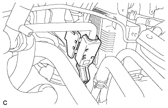
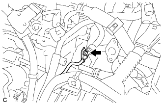
  1. Release the claw and remove the No. 1 fuel pipe clamp.


    A216404E01
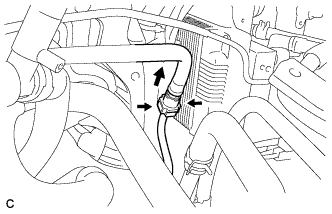
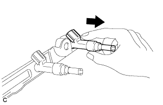
  1. Pinch the tube connector, and then pull the tube connector off of the pipe.

    NOTICE:
    1. Check for foreign matter in the fuel tube around the fuel tube connector. Clean it if necessary. Foreign matter can affect the ability of the O-ring to seal the connector and fuel pipe.
    2. Do not use any tools to separate the connector and pipe.
    3. Do not forcefully bend, kink or twist the hose.
    4. Keep the connector and pipe free from foreign matter.
    5. If the connector and pipe are stuck together, pinch the connector and turn it carefully to disconnect it.
    6. Put the connector in a plastic bag to prevent damage and contamination.


10. REMOVE FUEL DELIVERY PIPE SUB-ASSEMBLY


    A216399
  1. Remove the bolt.


    A216400
  1. Remove the 2 bolts and the fuel delivery pipe sub-assembly.

    NOTICE:
    Be careful not to drop the fuel injectors when removing the fuel delivery pipe.


11. REMOVE NO. 1 DELIVERY PIPE SPACER


    A216401
  1. Remove the 2 delivery pipe spacers from the cylinder head.


12. REMOVE FUEL INJECTOR ASSEMBLY


    A153009
  1. Pull the 4 fuel injector assemblies out of the fuel delivery pipe sub-assembly.

  1. Remove the O-ring from each fuel injector assembly.


    A171499
  1. For reinstallation, attach a tag or label to each injector shaft.

    NOTICE:
    Prevent entry of foreign objects by covering the fuel injectors with plastic bags.


    A216402
  1. Remove the 4 injector vibration insulators.