DTC B2762 Intrusion Sensor Signal Circuit Malfunction |
| DTC No. | DTC Detection Condition | Trouble Area |
| B2762 | After normal/trouble signal is output from intrusion sensor as result of self-diagnosis, following malfunctions are detected:
|
|
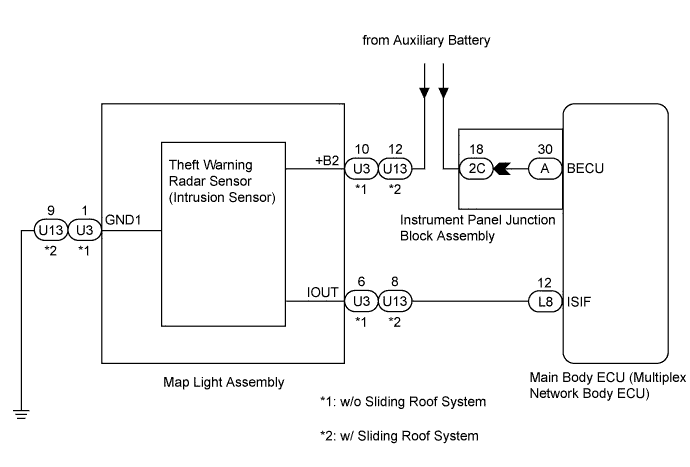
| 1.CHECK HARNESS AND CONNECTOR (MAIN BODY ECU - MAP LIGHT ASSEMBLY) |
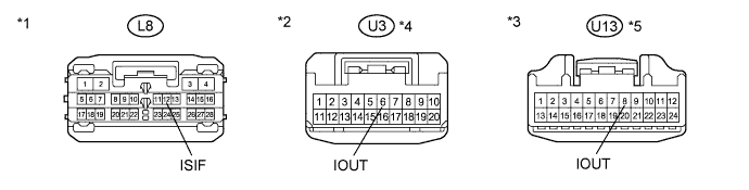
Disconnect the L8 main body ECU (multiplex network body ECU) and U3*4 or U13*5 map light assembly connectors.
Measure the resistance according to the value(s) in the table below.
| Tester Connection | Condition | Specified Condition |
| L8-12 (ISIF) - U3-6 (IOUT)*4 L8-12 (ISIF) - U13-8 (IOUT)*5 | Always | Below 1 Ω |
| L8-12 (ISIF) - Body ground | Always | 10 kΩ or higher |
| *1 | Front view of wire harness connector (to Main Body ECU (Multiplex Network Body ECU)) | *2 | Front view of wire harness connector (to Map Light Assembly (Intrusion Sensor)) |
| *3 | Front view of wire harness connector (to Map Light Assembly (Intrusion Sensor)) | *4 | w/o Sliding Roof System |
| *5 | w/ Sliding Roof System | - | - |
|
| ||||
| OK | |
| 2.REPLACE THEFT WARNING RADAR SENSOR (INTRUSION SENSOR) |
Replace the theft warning radar sensor (intrusion sensor) (Click here).
| NEXT | |
| 3.CHECK FOR DTC |
Check if DTC B2762 is not output (Click here).
|
| ||||
| OK | ||
| ||
