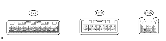
Terminal No. (Symbol)
| Wiring Color
| Terminal Description
| Condition
| Specified Condition
|
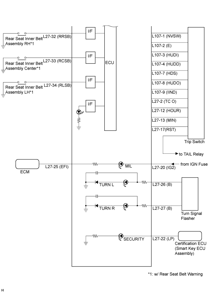
L27-2 (TC O)*1 - Body ground
| G - Body ground
| Trip switch signal (Unit change switch)
| Unit change switch not pressed
| 11 to 14 V
|
Unit change switch pressed
| Below 1 V
|
L27-2 (TC O)*2 - Body ground
| G - Body ground
| Trip switch signal (Tail cancel switch)
| Tail cancel switch not pressed
| 11 to 14 V
|
Tail cancel switch pressed
| Below 1 V
|
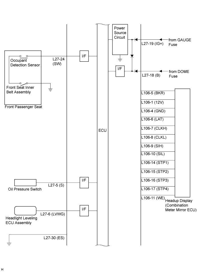
L27-5 (S) - Body ground
| R - Body ground
| Oil pressure switch signal
| Power switch on (IG), oil pressure warning display off
| Below 1 V
|
Power switch on (IG), oil pressure warning display comes on
| 11 to 14 V
|
L27-6 (LVWG) - Body ground
| L - Body ground
| Headlight leveling indicator light signal
| Power switch on (IG), headlight leveling indicator light off
| 11 to 14 V
|
Power switch on (IG), headlight leveling indicator light blinks
| Below 1 V ←→ 11 to 14 V
|
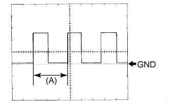
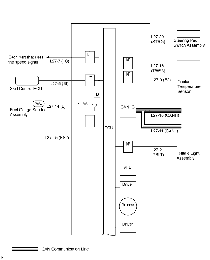
L27-7 (+S) - Body ground
| V - Body ground
| Speed signal for other systems (Output)
| Power switch on (IG), front wheel turns slowly
| Pulse generation
(See waveform 1)
|
L27-8 (SI) - Body ground
| V - Body ground
| Speed signal (Input)
| Power switch on (IG), front wheel turns slowly
| Pulse generation
(See waveform 1)
|
L27-9 (E2) - Body ground
| G - Body ground
| Ground (Coolant temperature sensor ground)
| Always
| Below 1 Ω
|
L27-10 (CANH) - Body ground
| P - Body ground
| CAN communication signal
| Power switch off
| 200 Ω or higher
|
L27-11 (CANL) - Body ground
| W - Body ground
| CAN communication signal
| Power switch off
| 200 Ω or higher
|
L27-12 (HOUR) - Body ground
| B - Body ground
| Trip switch signal (Hour adjust switch)
| Hour adjust switch not pressed
| 11 to 14 V
|
Hour adjust switch pressed
| Below 1 V
|
L27-13 (MIN) - Body ground
| B - Body ground
| Trip switch signal (Minute adjust switch)
| Minute adjust switch not pressed
| 11 to 14 V
|
Minute adjust switch pressed
| Below 1 V
|
L27-14 (L) - Body ground
| B - Body ground
| Fuel level signal
| Power switch on (IG), fuel level warning light OFF
| Below 1 V
|
Power switch on (IG), fuel level warning light ON
| 3 to 7 V
|
L27-15 (ES2) - Body ground
| W - Body ground
| Ground (Fuel ground)
| Always
| Below 1 Ω
|
L27-16 (TWS3) - Body ground
| B - Body ground
| Coolant temperature sensor signal
| Power switch on (IG), coolant temperature below 113°C (235°F)
| 0.2 to 4.8 V
|
Power switch on (IG), coolant temperature below 120°C (248°F) or more
| Below 0.15 V
|
L27-17 (RST) - Body ground
| R - Body ground
| Trip switch signal (Set switch)
| Set switch not pressed
| 11 to 14 V
|
Set switch pressed
| Below 1 V
|
L27-18 (B) - Body ground
| R - Body ground
| Battery
| Power switch off
| 11 to 14 V
|
L27-19 (IG+) - Body ground
| L - Body ground
| Power switch signal
| Power switch off
| Below 1 V
|
Power switch on (IG)
| 11 to 14 V
|
L27-20 (IG2) - Body ground
| G - Body ground
| Power switch signal
| Power switch off
| Below 1 V
|
Power switch on (IG)
| 11 to 14 V
|
L27-21 (PBLT) - Body ground
| Y - Body ground
| Front passenger side seat belt warning light signal
| Power switch on (IG), front passenger side seat belt warning light off
| 11 to 14 V
|
Power switch on (IG), front passenger side seat belt warning light blinks
| Below 1 V ←→ 11 to 14 V
|
L27-22 (LP) - Body ground
| B - Body ground
| Security indicator light signal
| Power switch on (IG), security indicator light off
| Below 2 V
|
Security indicator light blinks
| Pulse generation
|
L27-24 (SW) - Body ground
| P - Body ground
| Front passenger side seat belt buckle switch signal
| Power switch on (IG), sit on the front passenger seat, and front passenger side seat belt unfastened
| Below 1 V
|
Power switch on (IG), sit on the front passenger seat, and front passenger side seat belt fastened
| 11 to 14 V
|
L27-25 (EFI) - Body ground
| LG - Body ground
| MIL (Check engine warning light) signal
| Power switch on (IG), MIL (Check engine warning light) off
| 11 to 14 V
|
Power switch on (IG), MIL (Check engine warning light) comes on
| Below 1 V
|
L27-26 (B) - Body ground
| Y - Body ground
| Turn LH indicator light signal
| Power switch on (IG), turn LH indicator light off
| 11 to 14 V
|
Power switch on (IG), turn LH indicator light blinks
| Below 1 V ←→ 11 to 14 V
|
L27-27 (B) - Body ground
| G - Body ground
| Turn RH indicator light signal
| Power switch on (IG), turn RH indicator light off
| 11 to 14 V
|
Power switch on (IG), turn RH indicator light blinks
| Below 1 V ←→ 11 to 14 V
|
L27-29 (STRG) - Body ground
| G - Body ground
| Steering pad switch signal
| Always
| Pulse generation
|
L27-30 (ES) - Body ground
| BR - Body ground
| Ground (Signal ground)
| Always
| Below 1 Ω
|
L27-32 (RRSB)*3 - Body ground
| R - Body ground
| Rear RH passenger seat belt buckle switch signal
| Power switch on (IG), rear RH passenger seat belt unfastened
| Below 1 V
|
Power switch on (IG), rear RH passenger seat belt fastened
| 11 to 14 V
|
L27-33 (RCSB)*3 - Body ground
| L - Body ground
| Rear center passenger seat belt buckle switch signal
| Power switch on (IG), rear center passenger seat belt unfastened
| Below 1 V
|
Power switch on (IG), rear center passenger seat belt fastened
| 11 to 14 V
|
L27-34 (RLSB)*3 - Body ground
| Y - Body ground
| Rear left passenger seat belt buckle switch signal
| Power switch on (IG), rear left passenger seat belt unfastened
| Below 1 V
|
Power switch on (IG), rear left passenger seat belt fastened
| 11 to 14 V
|
L106-1 (12V) - Body ground
| B - Body ground
| Power switch signal
| Power switch off
| 11 to 14 V
|
L106-4 (GND) - Body ground
| W - Body ground
| Ground
| Always
| Below 1 Ω
|
L106-5 (BKR) - Body ground
| P - Body ground
| Headup display illumination signal
| Power switch on (IG)
| Pulse generation
|
L106-6 (LAT) - Body ground
| R - Body ground
| Headup display dot illumination timing signal
| Power switch on (IG)
| Pulse generation
|
L106-7 (CLKH) - Body ground
| R - Body ground
| Clock signal
| Always
| Pulse generation
|
L106-8 (CLKL) - Body ground
| G - Body ground
| Clock signal
| Always
| Pulse generation
|
L106-9 (SIH) - Body ground
| G - Body ground
| Headup display dot signal
| Power switch on (IG)
| Pulse generation
|
L106-10 (SIL) - Body ground
| R - Body ground
| Headup display dot signal
| Power switch on (IG)
| Pulse generation
|
L106-11 (WE) - Body ground
| L - Body ground
| Headup display dot illumination signal
| Power switch on (IG), headup display illuminated
| Pulse generation
|
L106-14 (STP1) - Body ground
| V - Body ground
| Stepper motor signal
| Power switch on (IG)
| Pulse generation
|
L106-15 (STP2) - Body ground
| LG - Body ground
| Stepper motor signal
| Power switch on (IG)
| Pulse generation
|
L106-16 (STP3) - Body ground
| B - Body ground
| Stepper motor signal
| Power switch on (IG)
| Pulse generation
|
L106-17 (STP4) - Body ground
| W - Body ground
| Stepper motor signal
| Power switch on (IG)
| Pulse generation
|
L107-1 (NVSW) - L107-2 (E)
| V - BE
| Navigation system display select switch signal
| Turn the power switch on (IG), navigation system display select switch not pressed
| Below 1 V
|
Turn the power switch on (IG), navigation system display select switch pressed
| 11 to 14 V
|
L107-2 (E) - Body ground
| BE - Body ground
| Ground
| Always
| Below 1 Ω
|
L107-3 (HUDI) - Body ground
| W - Body ground
| Headup display indicator light signal
| Turn the power switch on (IG), headup display indicator light goes off
| Below 1 V
|
Turn the power switch on (IG), headup display indicator light comes on
| 11 to 14 V
|
L107-4 (HUDD) - L107-2 (E)
| R - BE
| Headup display position down switch signal
| Turn the power switch on (IG), headup display position down switch not pressed
| Below 1 V
|
Turn the power switch on (IG), headup display position down switch pressed
| 11 to 14 V
|
L107-7 (HDS) - L107-2 (E)
| P - BE
| Headup display position up switch signal
| Turn the power switch on (IG), headup display position down switch not pressed
| Below 1 V
|
Turn the power switch on (IG), headup display position down switch pressed
| 11 to 14 V
|
L107-8 (HUDO) - L107-2 (E)
| B - BE
| Headup display mode select switch signal
| Turn the power switch on (IG), headup display mode select switch not pressed
| Below 1 V
|
Turn the power switch on (IG), headup display mode select switch pressed
| 11 to 14 V
|
L107-9 (IIND) - Body ground
| BE - Body ground
| Navigation system indicator light signal
| Turn the power switch on (IG), navigation system indicator light goes off
| Below 1 V
|
Turn the power switch on (IG), navigation system indicator light comes on
| 11 to 14 V
|