LIGHTING SYSTEM > Door Unlock Detection Switch Circuit |
| 1.READ VALUE USING INTELLIGENT TESTER |
Connect the intelligent tester to the DLC3.
Turn the power switch on (IG).
Turn the intelligent tester on.
Enter the following menus: Body / Main Body / Data List.
Read the display on the intelligent tester.
| Tester Display | Measurement Item/Range | Normal Condition | Diagnostic Note |
| FL Door Lock Pos | Front door unlock detection switch LH signal/ON or OFF | ON: Front door LH unlocked OFF: Front door LH locked | - |
| FR Door Lock Pos | Front door unlock detection switch RH signal/ON or OFF | ON: Front door RH unlocked OFF: Front door RH locked | - |
| RL-Door Lock Pos SW | Rear door unlock detection switch LH signal/ON or OFF | ON: Rear door LH or RH unlocked OFF: Rear door LH and RH locked | - |
| RR-Door Lock Pos SW | Rear door unlock detection switch RH signal/ON or OFF | ON: Rear door LH or RH unlocked OFF: Rear door LH and RH locked | - |
| Result | Proceed to |
| OK | A |
| Front door unlock detection switch LH does not operate | B |
| Front door unlock detection switch RH does not operate | C |
| Rear door unlock detection switch LH does not operate | D |
| Rear door unlock detection switch RH does not operate | E |
|
| ||||
|
| ||||
|
| ||||
|
| ||||
| A | ||
| ||
| 2.INSPECT FRONT DOOR LOCK ASSEMBLY LH |
Inspect the front door lock assembly LH (Click here).
|
| ||||
| OK | |
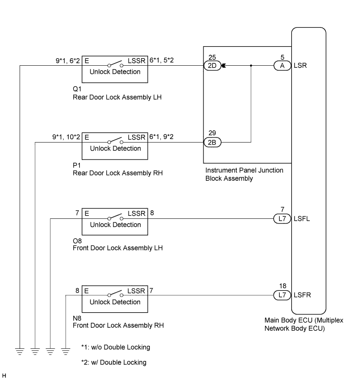
| 3.CHECK HARNESS AND CONNECTOR (FRONT DOOR LOCK ASSEMBLY LH - MAIN BODY ECU AND BODY GROUND) |
Disconnect the O8 front door lock assembly LH connector.
Disconnect the L7 main body ECU (multiplex network body ECU) connector.
Measure the resistance according to the value(s) in the table below.
| Tester Connection | Condition | Specified Condition |
| O8-8 (LSSR) - L7-7 (LSFL) | Always | Below 1 Ω |
| O8-8 (LSSR) - Body ground | Always | 10 kΩ or higher |
| O8-7 (E) - Body ground | Always | Below 1 Ω |
|
| ||||
| OK | ||
| ||
| 4.INSPECT FRONT DOOR LOCK ASSEMBLY RH |
Inspect the front door lock assembly RH (Click here).
|
| ||||
| OK | |
| 5.CHECK HARNESS AND CONNECTOR (FRONT DOOR LOCK ASSEMBLY RH - MAIN BODY ECU AND BODY GROUND) |
Disconnect the N8 front door lock assembly RH connector.
Disconnect the L7 main body ECU (multiplex network body ECU) connector.
Measure the resistance according to the value(s) in the table below.
| Tester Connection (Symbols) | Condition | Specified Condition |
| N8-7 (LSSR) - L7-18 (LSFR) | Always | Below 1 Ω |
| N8-7 (LSSR) - Body ground | Always | 10 kΩ or higher |
| N8-8 (E) - Body ground | Always | Below 1 Ω |
|
| ||||
| OK | ||
| ||
| 6.INSPECT REAR DOOR LOCK ASSEMBLY LH |
Inspect the rear door lock assembly LH (Click here).
|
| ||||
| OK | |
| Go to step 8 |
| 7.CHECK HARNESS AND CONNECTOR (REAR DOOR LOCK ASSEMBLY LH - MAIN BODY ECU AND BODY GROUND) |
Disconnect the Q1 rear door lock assembly LH connector.
Disconnect the 2D instrument panel junction block assembly connector.
Measure the resistance according to the value(s) in the table below.
| Tester Connection | Condition | Specified Condition |
| Q1-6 (LSSR) - 2D-25 | Always | Below 1 Ω |
| Q1-6 (LSSR) - Body ground | Always | 10 kΩ or higher |
| Q1-9 (E) - Body ground | Always | Below 1 Ω |
| Tester Connection | Condition | Specified Condition |
| Q1-5 (LSSR) - 2D-25 | Always | Below 1 Ω |
| Q1-5 (LSSR) - Body ground | Always | 10 kΩ or higher |
| Q1-6 (E) - Body ground | Always | Below 1 Ω |
|
| ||||
| OK | |
| 8.INSPECT INSTRUMENT PANEL JUNCTION BLOCK ASSEMBLY |
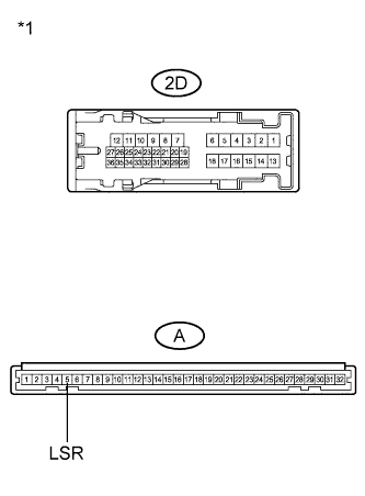 |
Remove the instrument panel junction block assembly.
Measure the resistance according to the value(s) in the table below.
| Tester Connection | Condition | Specified Condition |
| 2D-25 - A-5 (LSR) | Always | Below 1 Ω |
| 2D-25 - Body ground | Always | 10 kΩ or higher |
| *1 | Component without harness connected (Instrument Panel Junction Block Assembly) |
|
| ||||
| OK | ||
| ||
| 9.INSPECT REAR DOOR LOCK ASSEMBLY RH |
Inspect the rear door lock assembly RH (Click here).
|
| ||||
| OK | |
| 10.CHECK HARNESS AND CONNECTOR (REAR DOOR LOCK ASSEMBLY RH - MAIN BODY ECU AND BODY GROUND) |
Disconnect the P1 rear door lock assembly RH connector.
Disconnect the 2B main body ECU (multiplex network body ECU) connector.
Measure the resistance according to the value(s) in the table below.
| Tester Connection | Condition | Specified Condition |
| P1-6 (LSSR) - 2B-29 | Always | Below 1 Ω |
| P1-6 (LSSR) - Body ground | Always | 10 kΩ or higher |
| P1-9 (E) - Body ground | Always | Below 1 Ω |
| Tester Connection | Condition | Specified Condition |
| P1-9 (LSSR) - 2B-29 | Always | Below 1 Ω |
| P1-9 (LSSR) - Body ground | Always | 10 kΩ or higher |
| P1-10 (E) - Body ground | Always | Below 1 Ω |
|
| ||||
| OK | |
| 11.INSPECT INSTRUMENT PANEL JUNCTION BLOCK ASSEMBLY |
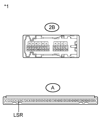 |
Remove the instrument panel junction block assembly.
Measure the resistance according to the value(s) in the table below.
| Tester Connection | Condition | Specified Condition |
| 2B-29 - A-5 (LSR) | Always | Below 1 Ω |
| 2B-29 - Body ground | Always | 10 kΩ or higher |
| *1 | Component without harness connected (Instrument Panel Junction Block Assembly) |
|
| ||||
| OK | ||
| ||
