NAVIGATION SYSTEM (for Navigation Receiver Type) > Parking Brake Switch Circuit |
| 1.CHECK BRAKE WARNING LIGHT |
Check that the brake warning light comes on when the parking brake is applied and goes off when it is released.
|
| ||||
| OK | |
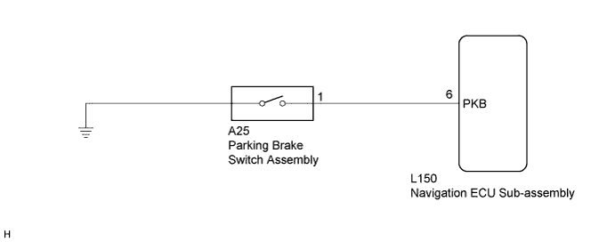
| 2.CHECK HARNESS AND CONNECTOR (PARKING BRAKE SWITCH ASSEMBLY - NAVIGATION ECU SUB-ASSEMBLY) |
Disconnect the navigation ECU sub-assembly connector.
Disconnect the parking brake switch assembly connector.
Measure the resistance according to the value(s) in the table below.
| Tester Connection | Condition | Specified Condition |
| L150-6 (PKB) - A25-1 | Always | Below 1 Ω |
| L150-6 (PKB) - Body ground | Always | 10 kΩ or higher |
|
| ||||
| OK | ||
| ||
