Home

Toyota Workshop

GSIC - Global Service Information Center

BRAKE PEDAL STROKE SENSOR (for RHD) > REMOVAL

for Preparation Click here


NOTICE:
While the battery is connected, even if the power switch is off, the brake control system activates when the brake pedal is depressed or any door courtesy switch turns on. Therefore, when servicing the brake system components, do not operate the brake pedal or open/close the doors while the battery is connected.


1. PRECAUTION

NOTICE:
After turning the power switch off, waiting time may be required before disconnecting the cable from the negative (-) battery terminal. Therefore, make sure to read the disconnecting the cable from the negative (-) battery terminal notices before proceeding with work (Click here).


2. REMOVE REAR NO. 2 FLOOR BOARD


    B227787E01
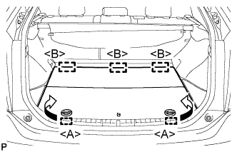
  1. Disengage the 2 guides <A> as shown in the illustration.

  1. Disengage the 3 guides <B> and remove the rear No. 2 floor board.


3. REMOVE REAR DECK FLOOR BOX
  1. Remove the rear deck floor box.


4. REMOVE REAR NO. 3 FLOOR BOARD


    B227791
  1. Disengage the 2 guides and remove the rear No. 3 floor board.


5. DISCONNECT CABLE FROM NEGATIVE BATTERY TERMINAL
  1. Disconnect the cable from the negative (-) battery terminal.

    CAUTION:
    Wait at least 90 seconds after disconnecting the cable from the negative (-) battery terminal to prevent airbag and seat belt pretensioner activation.

    NOTICE:
    When disconnecting the cable, some systems need to be initialized after the cable is reconnected (Click here).


6. REMOVE FRONT DOOR SCUFF PLATE RH

HINT:
Perform the same procedure as for the LHD (Click here).


7. REMOVE COWL SIDE TRIM SUB-ASSEMBLY RH

HINT:
Perform the same procedure as for the LHD (Click here).


8. REMOVE LOWER INSTRUMENT PANEL FINISH PANEL

HINT:
Perform the same procedure as for the LHD (Click here).


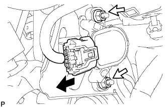
9. REMOVE ECU INTEGRATION BOX RH
  1. Disconnect the connectors.


    C208064
  1. Remove the nut, bolt and ECU integration box RH.


10. REMOVE BRAKE PEDAL STROKE SENSOR ASSEMBLY


    C233726
  1. Disconnect the connector from the brake pedal stroke sensor assembly.

  1. Remove the 2 nuts and brake pedal stroke sensor assembly.

    NOTICE:
    1. Do not drop the brake pedal stroke sensor assembly.
    2. If the brake pedal stroke sensor assembly has been dropped, replace the brake pedal stroke sensor assembly with a new one.