DTC C1311/11 Open in Main Relay 1 Circuit |
DTC C1312/12 Short in Main Relay 1 Circuit |
| DTC Code | INF Code | DTC Detection Condition | Trouble Area |
| C1311/11 | 1 | Either of the following is detected:
|
|
| C1312/12 | 2 | The ABS main relay contact is turned ON (BS terminal voltage 3.5 V or more) for 4.5 seconds or more when ABS main relay OFF is requested from the ECU. |
|
| 1.PERFORM ACTIVE TEST USING INTELLIGENT TESTER (ABS MAIN RELAY) |
Connect the intelligent tester to the DLC3.
Turn the power switch on (IG).
Select the Active Test on the intelligent tester (Click here).
| Tester Display | Test Part | Control Range | Diagnostic Note |
| ECB* Main Relay | ABS main relay | Relay ON/OFF | - |
Select the Data List on the intelligent tester (Click here).
| Tester Display | Measurement Item/Range | Normal Condition | Diagnostic Note |
| ECB* Main Relay | ABS main relay / ON or OFF | ON: Relay on OFF: Relay off | - |
Check the operating condition of the ABS main relay when operating it with the intelligent tester.
| Result | Proceed to |
| ABS main relay in the Data List turns ON/OFF using the Active Test | A |
| ABS main relay in the Data List does not change using the Active Test | B |
|
| ||||
| A | |
| 2.INSPECT SKID CONTROL ECU (BS TERMINAL) |
 |
Turn the power switch off.
Make sure that there is no looseness at the locking part and the connecting part of the connector.
Disconnect the skid control ECU connector.
Measure the voltage according to the value(s) in the table below.
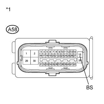
| Tester Connection | Condition | Specified Condition |
| A58-15 (BS) - Body ground | Always | 11 to 14 V |
| *1 | Front view of wire harness connector (to Skid Control ECU) |
|
| ||||
| OK | |
| 3.RECONFIRM DTC |
Reconnect the skid control ECU connector.
Clear the DTCs (Click here).
Turn the power switch on (IG).
Check if the same DTC is recorded (Click here).
| Result | Proceed to |
| DTCs (C1311/11and C1312/12) are not output | A |
| DTCs (C1311/11 and/or C1312/12) are output (for LHD) | B |
| DTCs (C1311/11 and/or C1312/12) are output (for RHD) | C |
|
| ||||
|
| ||||
| A | ||
| ||
| 4.INSPECT ABS MAIN FUSES |
 |
Turn the power switch off.
Remove the ABS MAIN fuses from the engine room relay block.
Measure the resistance according to the value(s) in the table below.
| Tester Connection | Condition | Specified Condition |
| ABS MAIN NO. 1 (20 A) fuse | Always | Below 1 Ω |
| ABS MAIN NO. 2 (7.5 A) fuse | Always | Below 1 Ω |
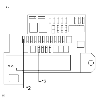
| *1 | Engine Room Relay Block |
| *2 | ABS MAIN NO. 1 Fuse |
| *3 | ABS MAIN NO. 2 Fuse |
|
| ||||
| OK | |
| 5.INSPECT SKID CONTROL ECU (BI TERMINAL) |
 |
Install the ABS MAIN fuses.
Make sure that there is no looseness at the locking part and the connecting part of the connector.
Disconnect the skid control ECU connector.
Measure the voltage according to the value(s) in the table below.
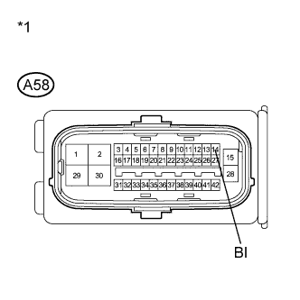
| Tester Connection | Condition | Specified Condition |
| A58-14 (BI) - Body ground | Always | 11 to 14 V |
| *1 | Front view of wire harness connector (to Skid Control ECU) |
|
| ||||
| OK | |
| 6.INSPECT SKID CONTROL ECU (BS TERMINAL) |
|
Measure the voltage according to the value(s) in the table below.
| Tester Connection | Condition | Specified Condition |
| A58-15 (BS) - Body ground | Always | 11 to 14 V |
| *1 | Front view of wire harness connector (to Skid Control ECU) |
| Result | Proceed to |
| OK (for LHD) | A |
| OK (for RHD) | B |
| NG | C |
|
| ||||
|
| ||||
| A | ||
| ||
