DTC P0A90-251 Drive Motor "A" Performance |
| DTC No. | INF Code | DTC Detection Condition | Trouble Area |
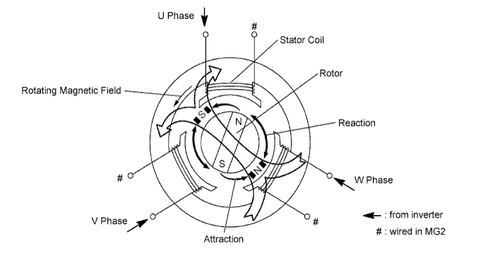
| P0A90 | 251 | Motor magnetic force deterioration or same phase short circuit |
|
| 1.CHECK DTC OUTPUT (HV) |
Connect the intelligent tester to the DLC3.
Turn the power switch on (IG).
Enter the following menus: Powertrain / Hybrid Control / Trouble Codes.
Check if DTCs are output.
| Result | Proceed to |
| P0A90-251 only is output. | A |
| Any of the following DTCs are also output. | B |
| DTC No. | Relevant Diagnosis |
| P0A1A (all INF codes)*1 | Generator Control Module |
| P0A1B (all INF codes)*1 | Drive Motor "A" Control Module |
| P0A1D (all INF codes)*1 | Hybrid Powertrain Control Module |
| P0A60 (all INF codes)*1 | Drive Motor "A" Phase V Current |
| P0A63 (all INF codes)*1 | Drive Motor "A" Phase W Current |
| P0A72 (all INF codes)*1 | Generator Phase V Current |
| P0A75 (all INF codes)*1 | Generator Phase W Current |
| P0A3F-243 | Drive Motor "A" Position Sensor Circuit |
| P0A40-500 | Drive Motor "A" Position Sensor Circuit Range/Performance |
| P0A41-245 | Drive Motor "A" Position Sensor Circuit Low |
| P0A4B-253 | Generator Position Sensor Circuit |
| P0A4C-513 | Generator Position Sensor Circuit Range/Performance |
| P0A4D-255 | Generator Position Sensor Circuit Low |
| P0A51-174 | Drive Motor "A" Current Sensor Circuit |
| P0A78-202, 266, 267, 306, 510, 586 | Drive Motor "A" Inverter Performance |
| P0A7A-344, 522 | Generator Inverter Performance |
| P0A90-509 | Drive Motor "A" Performance |
| P0A92-521 | Hybrid Generator Performance |
| P0A94-585, 587, 589, 590 | DC / DC Converter Performance |
| P0AA6 (all INF codes)*1 | Hybrid Battery Voltage System Isolation Fault |
| P0C76-523 | Hybrid Battery System Discharge Time Too Long |
| P3004-132 | Power Cable Malfunction |
| P3233-750 | Short to B+ in Blocking of HV Gate Connection |
Turn the power switch off.
|
| ||||
| A | |
| 2.SIMULATION TEST |
Connect the intelligent tester to the DLC3.
Turn the power switch on (IG).
Test-drive the vehicle at a speed of 25 mph (40 km/h) for approximately 1 minute.
Enter the following menus: Powertrain / Hybrid Control / Trouble Codes.
Check if DTCs are output.
| Result | Proceed to |
| P0A90-251 is output or no DTC is output. | A |
| P0A78-306 or P0A90-509 is output. | B |
Turn the power switch off.
|
| ||||
| A | |
| 3.CHECK CONNECTOR CONNECTION CONDITION (INVERTER WITH CONVERTER ASSEMBLY CONNECTOR) |
 |
Check that the service plug grip is not installed.
Check the connection of the low voltage connector of the inverter with converter assembly.
|
| ||||
| OK | |
| 4.CHECK INVERTER WITH CONVERTER ASSEMBLY (MOTOR CABLE CONNECTION CONDITION) |
Check that the service plug grip is not installed.
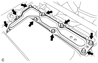 |
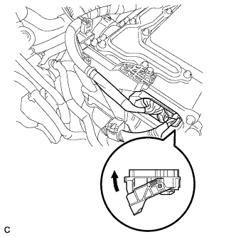
Remove the inverter terminal cover from the inverter with converter assembly.
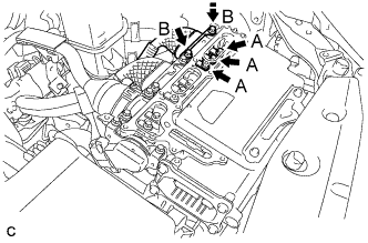 |
Check that the bolts for the motor cable are tightened to the specified torque, the motor cable is connected securely, and there are no contact problems.
Disconnect the motor cable from the inverter with converter assembly.
Check for arc marks at the bolts for the motor cable.
| Result | Proceed to | |
| The terminals are connected securely and there are no contact problems. | There are no arc marks. | A |
| The terminals are not connected securely and there is a contact problem. | There are arc marks. | B |
| The terminals are not connected securely and there is a contact problem. | There are no arc marks. | C |
| The terminals are connected securely and there are no contact problems. | There are arc marks. | B |
Connect the motor cable to the inverter with converter assembly.
Install the inverter terminal cover.
|
| ||||
|
| ||||
| A | |
| 5.CHECK HYBRID VEHICLE TRANSAXLE ASSEMBLY (MOTOR CABLE CONNECTION CONDITION) |
Check that the service plug grip is not installed.
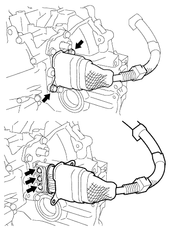 |
Check that the bolts for the motor cable are tightened to the specified torque, the motor cable is connected securely, and there are no contact problems.
Disconnect the motor cable from the hybrid transaxle assembly.
Check for arc marks at the bolts for the motor cable.
| Result | Proceed to | |
| The terminals are connected securely and there are no contact problems. | There are no arc marks. | A |
| The terminals are not connected securely and there is a contact problem. | There are arc marks. | B |
| The terminals are not connected securely and there is a contact problem. | There are no arc marks. | C |
| The terminals are connected securely and there are no contact problems. | There are arc marks. | B |
Connect the motor cable to the hybrid transaxle assembly.
|
| ||||
|
| ||||
| A | |
| 6.CHECK MOTOR CABLE |
Check that the service plug grip is not installed.
Remove the motor cable.
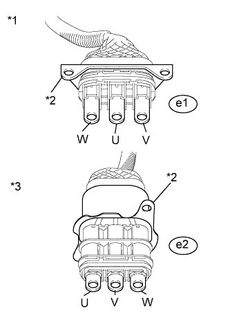 |
Using a megohmmeter set to 500 V, measure the resistance according to the value(s) in the table below.
| Tester Connection | Switch Condition | Specified Condition |
| e1-2 (U) - Body ground and shield ground | Power switch off | 100 MΩ or higher |
| e1-3 (V) - Body ground and shield ground | Power switch off | 100 MΩ or higher |
| e1-1 (W) - Body ground and shield ground | Power switch off | 100 MΩ or higher |
| *1 | Motor Cable (Inverter with Converter Assembly Side) |
| *2 | Shielded ground |
| *3 | Motor Cable (Hybrid Vehicle Transaxle Assembly Side) |
Measure the resistance according to the value(s) in the table below.
| Tester Connection | Switch Condition | Specified Condition |
| e1-2 (U) - e2-3 (U) | Power switch off | Below 1 Ω |
| e1-3 (V) - e2-2 (V) | Power switch off | Below 1 Ω |
| e1-1 (W) - e2-1 (W) | Power switch off | Below 1 Ω |
| e1-2 (U) - e2-2 (V) | Power switch off | 100 MΩ or higher |
| e1-3 (V) - e2-1 (W) | Power switch off | 100 MΩ or higher |
| e1-1 (W) - e2-3 (U) | Power switch off | 100 MΩ or higher |
Install the motor cable.
|
| ||||
| OK | ||
| ||
