DTC C1256/56 Accumulator Low Pressure |
| DTC Code | INF Code | DTC Detection Condition | Trouble Area |
| C1256/56 | 341 | Significant drop in accumulator pressure continues. (DTCs will be stored and the buzzer will operate when either condition is met.) |
|
| 1.BRAKE PROBLEM CHECK |
Ask the customer if frequent braking was performed while the brake warning light / yellow (minor malfunction) was on.
| Result | Proceed to |
| Frequent braking was not performed | A |
| Frequent braking was performed | B |
|
| ||||
| A | |
| 2.INSPECT BRAKE BOOSTER PUMP |
 |
Make sure that there is no looseness at the locking part and the connecting part of the connectors.
Disconnect the brake booster pump connectors.
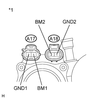
Measure the resistance according to the value(s) in the table below.
| Tester Connection | Condition | Specified Condition |
| A17-1 (BM1) - A17-2 (GND1) | Always | Below 10 Ω |
| A18-2 (BM2) - A18-1 (GND2) | Always | Below 10 Ω |
| A17-1 (BM1) - A18-2 (BM2) | Always | Below 1 Ω |
| A17-2 (GND1) - A18-1 (GND2) | Always | Below 1 Ω |
| *1 | Component without harness connected (Brake Booster Pump) |
|
| ||||
| OK | |
| 3.READ VALUE USING INTELLIGENT TESTER (ACCUMULATOR PRESSURE SENSOR) |
Reconnect the brake booster pump connectors.
Connect the intelligent tester to the DLC3.
Turn the power switch on (IG).
Select the Data List on the intelligent tester (Click here).
| Tester Display | Measurement Item/Range | Normal Condition | Diagnostic Note |
| Accumulator Sensor | Accumulator pressure sensor / Min.: 0 V, Max.: 5 V | Specified value: 2.9 to 4.2 V | When brake fluid is stored in the accumulator: Accumulator pressure changes in accordance with volume of fluid stored in the accumulator |
Wait for 30 seconds without depressing the brake pedal.
Check that the accumulator pressure sensor output values change is within the specified range.
|
| ||||
| OK | ||
| ||
| 4.PERFORM ACTIVE TEST USING INTELLIGENT TESTER (SOLENOID VALVE) |
Turn the power switch off.
Connect the intelligent tester to the DLC3.
Turn the power switch on (IG).
Select the Active Test on the intelligent tester (Click here).
| Tester Display | Test Part | Control Range | Diagnostic Note |
| ECB* Solenoid (SMC/SRC/SCC) | Switching solenoid valve (SMC/SRC/SCC) | Solenoid ON/OFF | Operation sound of solenoid (clicking sound) can be heard |
Perform the Active Test of the solenoid using the intelligent tester.
Select the Data List on the intelligent tester (Click here).
| Tester Display | Measurement Item/Range | Normal Condition | Diagnostic Note |
| Wheel Cylinder Pressure Sensor | Wheel cylinder pressure sensor / Min.: 0 V, Max.: 5 V | When brake pedal released: 0.1 to 0.9 V | Reading increases when brake pedal is depressed |
Check that the output value of wheel cylinder does not increase.
| Result | Proceed to |
| OK | A |
| NG (for LHD) | B |
| NG (for RHD) | C |
|
| ||||
|
| ||||
| A | ||
| ||
