Home

Toyota Workshop

GSIC - Global Service Information Center

DTC    P324E-788    MG-ECU Power Relay Intermittent Circuit

for Preparation Click here


DESCRIPTION

If the inverter with converter assembly (MG ECU) is reset due to a problem with the power source in the inverter, the power management control ECU (HV CPU) will set this DTC.

DTC No.
INF Code
DTC Detection Condition
Trouble Area
P324E
788
Error in reset signal from the inverter assembly power source IC
  1. Wire harness or connector
  2. Inverter with converter assembly
  3. Engine room junction block assembly
  4. Power management control ECU

WIRING DIAGRAM


A206502E03


INSPECTION PROCEDURE

CAUTION:
  1. Before inspecting the high-voltage system or disconnecting the low voltage connector of the inverter with converter assembly, take safety precautions such as wearing insulated gloves and removing the service plug grip to prevent electrical shocks. After removing the service plug grip, put it in your pocket to prevent other technicians from accidentally reconnecting it while you are working on the high-voltage system.
  2. After disconnecting the service plug grip, wait for at least 10 minutes before touching any of the high-voltage connectors or terminals. After waiting for 10 minutes, check the voltage at the terminals in the inspection point in the inverter with converter assembly. The voltage should be 0 V before beginning work.

HINT:
Waiting for at least 10 minutes is required to discharge the high-voltage capacitor inside the inverter with converter assembly.

1.CHECK DTC OUTPUT (HV)
  1. Connect the intelligent tester to the DLC3.

  1. Turn the power switch on (IG).

  1. Enter the following menus: Powertrain / Hybrid Control / Trouble Codes.

  1. Check if DTCs are output.

    Result:
    Result
    Proceed to
    P324E-788 only is output.
    A
    U0110-159, 160, 656, 657 are also output.
    B

  1. Turn the power switch off.


B
GO TO DTC CHART (Click here)
A


2.CHECK CONNECTOR CONNECTION CONDITION (INVERTER WITH CONVERTER ASSEMBLY CONNECTOR)
A214648

CAUTION:
Be sure to wear insulated gloves.

  1. Check that the service plug grip is not installed.

    NOTICE:
    After removing the service plug grip, do not turn the power switch on (READY), unless instructed by the repair manual because this may cause a malfunction.

NOTICE:
Before disconnecting the connector, confirm that it is properly connected by checking that the locking claws are engaged and that the connector does not pull out.

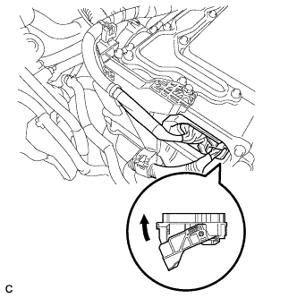
  1. Check the connection of the low voltage connector of the inverter with converter assembly.

    OK:
    The connector is connected securely and there are no contact problems.

    HINT:
    When connecting the connector, insert it with the locking lever in the raised position. Rotate the lever downward and make sure that the connector is pulled into its socket. When the locking lever is in its fully closed position, a click will be heard as its locking claws engage. After the click is heard, pull up on the connector to confirm that it is properly connected.


NG
CONNECT SECURELY
OK


3.CHECK HARNESS AND CONNECTOR (INVERTER WITH CONVERTER ASSEMBLY - IGCT RELAY)

CAUTION:
Be sure to wear insulated gloves.

  1. Check that the service plug grip is not installed.

    NOTICE:
    After removing the service plug grip, do not turn the power switch on (READY), unless instructed by the repair manual because this may cause a malfunction.

  1. Disconnect connector A59 from the inverter with converter assembly.

  1. Remove the IGCT relay from the engine room junction block assembly.


  1. Measure the resistance according to the value(s) in the table below.
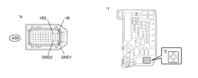

    A270318E02


    Text in Illustration 
    *1
    Engine Room Junction Block Assembly
    *2
    IGCT Relay
    *a
    Front view of wire harness connector
    (to Inverter with Converter Assembly)
    -
    -

    Standard Resistance (Check for open):
    Tester Connection
    Switch Condition
    Specified Condition
    A59-10 (+B) - 5
    Power switch off
    Below 1 Ω
    A59-9 (+B2) - 5
    Power switch off
    Below 1 Ω
    A59-28 (GND1) - Body ground
    Power switch off
    Below 1 Ω
    A59-27 (GND2) - Body ground
    Power switch off
    Below 1 Ω

    Standard Resistance (Check for short):
    Tester Connection
    Switch Condition
    Specified Condition
    A59-10 (+B) or A59-9 (+B2) - Body ground and other terminals
    Power switch off
    10 kΩ or higher

  1. Install the IGCT relay.

  1. Connect the power management control ECU connector.


NG
REPAIR OR REPLACE HARNESS OR CONNECTOR
OK

REPLACE INVERTER WITH CONVERTER ASSEMBLY (Click here)