DTC P0A1A-200 Generator Control Module |
DTC P0A1A-792 Generator Control Module |
DTC P0A1A-793 Generator Control Module |
| DTC No. | INF Code | DTC Detection Condition | Trouble Area |
| P0A1A | 200 | The difference between the resolver angle for control and estimated resolver angle exceeds the allowable value. |
|
| 792 | Resolver REF signal cycle error | ||
| 793 | Resolver REF signal oscillation stop error |
| 1.CHECK DTC OUTPUT (HV) |
Connect the intelligent tester to the DLC3.
Turn the power switch on (IG).
Enter the following menus: Powertrain / Hybrid Control / Trouble Codes.
Check if DTCs are output.
| Result | Proceed to |
| P0A1A-200, 792, or 793 only is output. | A |
| Any of the following DTCs are also output. | B |
| DTC No. | Relevant Diagnosis |
| P0A3F-243 | Drive Motor "A" Position Sensor Circuit |
| P0A4B-253 | Generator Position Sensor Circuit |
| P0A4C-513 | Generator Position Sensor Circuit Range / Performance |
| P0A4D-255 | Generator Position Sensor Circuit Low |
Turn the power switch off.
|
| ||||
| A | |
| 2.CHECK CONNECTOR CONNECTION CONDITION (INVERTER WITH CONVERTER ASSEMBLY CONNECTOR) |
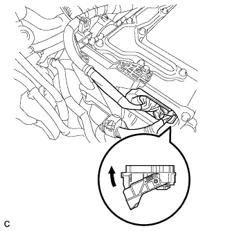 |
Check that the service plug grip is not installed.
Check the connection of the low voltage connector of the inverter with converter assembly.
|
| ||||
| OK | |
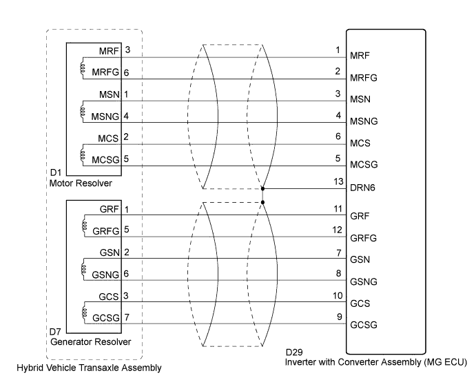
| 3.CHECK HARNESS AND CONNECTOR (INVERTER WITH CONVERTER ASSEMBLY - GENERATOR RESOLVER) |
Disconnect the low voltage connector D29 from the inverter with converter assembly.
Turn the power switch on (IG).
 |
Measure the voltage according to the value(s) in the table below.
| Tester Connection | Switch Condition | Specified Condition |
| D29-11 (GRF) - Body ground | Power switch on (IG) | Below 1 V |
| D29-12 (GRFG) - Body ground | Power switch on (IG) | Below 1 V |
| D29-7 (GSN) - Body ground | Power switch on (IG) | Below 1 V |
| D29-8 (GSNG) - Body ground | Power switch on (IG) | Below 1 V |
| D29-10 (GCS) - Body ground | Power switch on (IG) | Below 1 V |
| D29-9 (GCSG) - Body ground | Power switch on (IG) | Below 1 V |
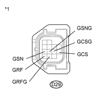
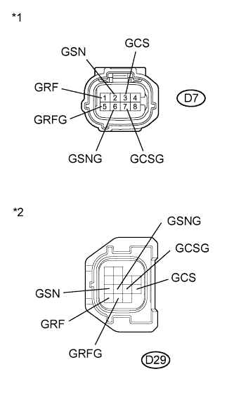
| *1 | Front view of wire harness connector (to Inverter with Converter Assembly) |
Turn the power switch off.
Connect the low voltage connector from the inverter with converter assembly.
|
| ||||
| OK | |
| 4.CHECK GENERATOR RESOLVER |
Disconnect the low voltage connector D29 from the inverter with converter assembly.
|
Measure the resistance according to the value(s) in the table below.
| Tester Connection | Switch Condition | Specified Condition |
| D29-11 (GRF) - D29-12 (GRFG) | Power switch off | 7.1 to 21.6 Ω |
| D29-7 (GSN) - D29-8 (GSNG) | Power switch off | 13.7 to 34.5 Ω |
| D29-10 (GCS) - D29-9 (GCSG) | Power switch off | 12.8 to 32.4 Ω |
| Tester Connection | Switch Condition | Specified Condition |
| D29-11 (GRF) or D29-12 (GRFG) - Body ground and other terminals | Power switch off | 1 MΩ or higher |
| D29-7 (GSN) or D29-8 (GSNG) - Body ground and other terminals | Power switch off | 1 MΩ or higher |
| D29-10 (GCS) or D29-9 (GCSG) - Body ground and other terminals | Power switch off | 1 MΩ or higher |
| *1 | Front view of wire harness connector (to Inverter with Converter Assembly) |
Connect the inverter with converter assembly connector.
|
| ||||
| OK | |
| 5.CHECK HARNESS AND CONNECTOR (INVERTER WITH CONVERTER ASSEMBLY - MOTOR RESOLVER) |
Disconnect the low voltage connector D29 from the inverter with converter assembly.
Turn the power switch on (IG).
 |
Measure the voltage according to the value(s) in the table below.
| Tester Connection | Switch Condition | Specified Condition |
| D29-1 (MRF) - Body ground | Power switch on (IG) | Below 1 V |
| D29-2 (MRFG) - Body ground | Power switch on (IG) | Below 1 V |
| D29-3 (MSN) - Body ground | Power switch on (IG) | Below 1 V |
| D29-4 (MSNG) - Body ground | Power switch on (IG) | Below 1 V |
| D29-6 (MCS) - Body ground | Power switch on (IG) | Below 1 V |
| D29-5 (MCSG) - Body ground | Power switch on (IG) | Below 1 V |
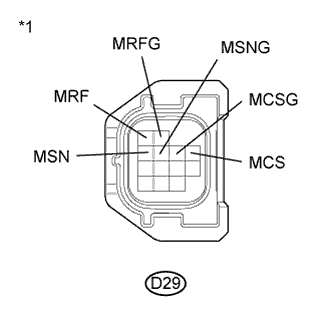
| *1 | Front view of wire harness connector (to Inverter with Converter Assembly) |
Turn the power switch off.
Connect the inverter with converter assembly connector.
|
| ||||
| OK | |
| 6.CHECK MOTOR RESOLVER |
Disconnect the low voltage connector D29 from the inverter with converter assembly.
|
Measure the resistance according to the value(s) in the table below.
| Tester Connection | Switch Condition | Specified Condition |
| D29-1 (MRF) - D29-2 (MRFG) | Power switch off | 7.1 to 21.6 Ω |
| D29-3 (MSN) - D29-4 (MSNG) | Power switch off | 13.7 to 34.5 Ω |
| D29-6 (MCS) - D29-5 (MCSG) | Power switch off | 12.8 to 32.4 Ω |
| Tester Connection | Switch Condition | Specified Condition |
| D29-1 (MRF) or D29-2 (MRFG) - Body ground and other terminals | Power switch off | 1 MΩ or higher |
| D29-3 (MSN) or D29-4 (MSNG) - Body ground and other terminals | Power switch off | 1 MΩ or higher |
| D29-6 (MCS) or D29-5 (MCSG) - Body ground and other terminals | Power switch off | 1 MΩ or higher |
| *1 | Front view of wire harness connector (to Inverter with Converter Assembly) |
Connect the inverter with converter assembly connector.
|
| ||||
| OK | |
| 7.CHECK CONNECTOR CONNECTION CONDITION (GENERATOR RESOLVER CONNECTOR) |
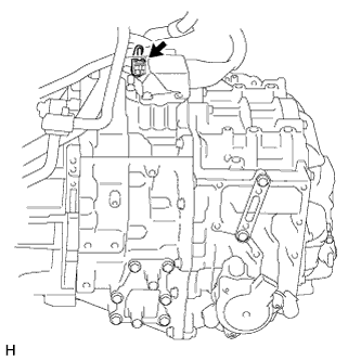 |
Check the connection of the generator resolver connector.
|
| ||||
| OK | |
| 8.CHECK CONNECTOR CONNECTION CONDITION (MOTOR RESOLVER CONNECTOR) |
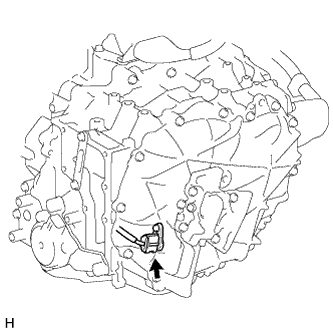 |
Check the connection of the motor resolver connector.
|
| ||||
| OK | ||
| ||
| 9.CHECK CONNECTOR CONNECTION CONDITION (GENERATOR RESOLVER CONNECTOR) |
|
Check the connection of the generator resolver connector.
|
| ||||
| OK | |
| 10.CHECK HARNESS AND CONNECTOR (INVERTER WITH CONVERTER ASSEMBLY - GENERATOR RESOLVER) |
Disconnect the low voltage connector D29 from the inverter with converter assembly.
 |
Disconnect the generator resolver connector.
Measure the resistance according to the value(s) in the table below.
| Tester Connection | Switch Condition | Specified Condition |
| D7-1 (GRF) - D29-11 (GRF) | Power switch off | Below 1 Ω |
| D7-5 (GRFG) - D29-12 (GRFG) | Power switch off | Below 1 Ω |
| D7-2 (GSN) - D29-7 (GSN) | Power switch off | Below 1 Ω |
| D7-6 (GSNG) - D29-8 (GSNG) | Power switch off | Below 1 Ω |
| D7-3 (GCS) - D29-10 (GCS) | Power switch off | Below 1 Ω |
| D7-7 (GCSG) - D29-9 (GCSG) | Power switch off | Below 1 Ω |
| Tester Connection | Switch Condition | Specified Condition |
| D7-1 (GRF) or D29-11 (GRF) - Body ground and other terminals | Power switch off | 1 MΩ or higher |
| D7-5 (GRFG) or D29-12 (GRFG) - Body ground and other terminals | Power switch off | 1 MΩ or higher |
| D7-2 (GSN) or D29-7 (GSN) - Body ground and other terminals | Power switch off | 1 MΩ or higher |
| D7-6 (GSNG) or D29-8 (GSNG) - Body ground and other terminals | Power switch off | 1 MΩ or higher |
| D7-3 (GCS) or D29-10 (GCS) - Body ground and other terminals | Power switch off | 1 MΩ or higher |
| D7-7 (GCSG) or D29-9 (GCSG) - Body ground and other terminals | Power switch off | 1 MΩ or higher |
| *1 | Front view of wire harness connector (to Generator Resolver) |
| *2 | Front view of wire harness connector (to Inverter with Converter Assembly) |
Connect the generator resolver connector.
Connect the inverter with converter assembly connector.
|
| ||||
| OK | ||
| ||
| 11.CHECK CONNECTOR CONNECTION CONDITION (MOTOR RESOLVER CONNECTOR) |
|
Check the connection of the motor resolver connector.
|
| ||||
| OK | |
| 12.CHECK HARNESS AND CONNECTOR (INVERTER WITH CONVERTER ASSEMBLY - MOTOR RESOLVER) |
Disconnect the low voltage connector D29 from the inverter with converter assembly.
 |
Disconnect the motor resolver connector.
Measure the resistance according to the value(s) in the table below.
| Tester Connection | Switch Condition | Specified Condition |
| D1-3 (MRF) - D29-1 (MRF) | Power switch off | Below 1 Ω |
| D1-6 (MRFG) - D29-2 (MRFG) | Power switch off | Below 1 Ω |
| D1-1 (MSN) - D29-3 (MSN) | Power switch off | Below 1 Ω |
| D1-4 (MSNG) - D29-4 (MSNG) | Power switch off | Below 1 Ω |
| D1-2 (MCS) - D29-6 (MCS) | Power switch off | Below 1 Ω |
| D1-5 (MCSG) - D29-5 (MCSG) | Power switch off | Below 1 Ω |
| Tester Connection | Switch Condition | Specified Condition |
| D1-3 (MRF) or D29-1 (MRF) - Body ground and other terminals | Power switch off | 1 MΩ or higher |
| D1-6 (MRFG) or D29-2 (MRFG) - Body ground and other terminals | Power switch off | 1 MΩ or higher |
| D1-1 (MSN) or D29-3 (MSN) - Body ground and other terminals | Power switch off | 1 MΩ or higher |
| D1-4 (MSNG) or D29-4 (MSNG) - Body ground and other terminals | Power switch off | 1 MΩ or higher |
| D1-2 (MCS) or D29-6 (MCS) - Body ground and other terminals | Power switch off | 1 MΩ or higher |
| D1-5 (MCSG) or D29-5 (MCSG) - Body ground and other terminals | Power switch off | 1 MΩ or higher |
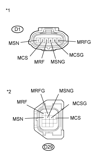
| *1 | Front view of wire harness connector (to Motor Resolver) |
| *2 | Front view of wire harness connector (to Inverter with Converter Assembly) |
Connect the motor resolver connector.
Connect the inverter with converter assembly connector.
|
| ||||
| OK | ||
| ||
