Home

Toyota Workshop

GSIC - Global Service Information Center

DTC    P0C3E-628    DC / DC Converter Temperature Sensor "B" Range / Performance

DTC    P0C41-627    DC / DC Converter Temperature Sensor "B" Intermittent / Erratic

for Preparation Click here


DESCRIPTION

The MG ECU located in the inverter with converter assembly detects the temperature of the boost converter using the temperature sensor built into the boost converter. If necessary, the MG ECU will limit inverter output to help prevent boost converter overheating. The power management control ECU (HV CPU) also detects malfunctions in the sensor based on the temperature sensor values. The inverter with converter assembly detects malfunctions in the boost converter temperature sensor and its wiring.

DTC No.
INF Code
DTC Detection Condition
Trouble Area
P0C3E
628
Boost converter temperature (lower) calculated by the power management control ECU is different from the actual temperature for 10 seconds or more, and the boost converter temperature (lower) is too high.
(1 trip detection logic)
  1. Inverter cooling system
  2. Cooling fan system
  3. Inverter with converter assembly
P0C41
627
Unusual sudden change in boost converter temperature sensor (lower) output occurs and the offset continues, or unusual sudden change in boost converter temperature sensor (lower) output occurs repeatedly.
(1 trip detection logic)

INSPECTION PROCEDURE

CAUTION:
  1. Before inspecting the high-voltage system or disconnecting the low voltage connector of the inverter with converter assembly, take safety precautions such as wearing insulated gloves and removing the service plug grip to prevent electrical shocks. After removing the service plug grip, put it in your pocket to prevent other technicians from accidentally reconnecting it while you are working on the high-voltage system.
  2. After disconnecting the service plug grip, wait for at least 10 minutes before touching any of the high-voltage connectors or terminals. After waiting for 10 minutes, check the voltage at the terminals in the inspection point in the inverter with converter assembly. The voltage should be 0 V before beginning work.

    HINT:
    Waiting for at least 10 minutes is required to discharge the high-voltage capacitor inside the inverter with converter assembly.

HINT:
After the repair, clear the DTCs and perform the following procedure to check that DTCs are not output.
  1. Turn the power switch on (READY) and wait for 120 seconds or more.
  2. Perform a road test according to the freeze frame data item "Vehicle Spd" for approximately 10 minutes.
    1. During the road test, check that the Data List items "Inverter Coolant Water Temperature", "Cnv Tmp (Upper)", "Cnv Temp (Lower)" and "Inverter W/P Revolution" are within the specified range to prevent the boost converter from overheating.

1.CHECK DTC OUTPUT (HV)
  1. Connect the intelligent tester to the DLC3.

  1. Turn the power switch on (IG).

  1. Enter the following menus: Powertrain / Hybrid Control / Trouble Codes.

  1. Check if DTCs are output.

    Result:
    Result
    Proceed to
    P0C3E-628 or P0C41-627 is output
    A
    Any of the following DTCs are also output.
    B


    DTC No.
    Relevant Diagnosis
    P0A93-346
    Inverter Cooling System Performance
    P0C73-776
    Motor Electronics Coolant Pump "A" Control Performance
    P314A-828
    Inverter Coolant Pump Speed Signal

    HINT:
    P0C3E-628 or P0C41-627 may be set due to a malfunction which also causes DTCs in the preceding table to be set. In this case, first troubleshoot the output DTCs in the preceding table. Then, perform a test to attempt to reproduce the problems, and check that no DTCs are output.

  1. Turn the power switch off.


B
GO TO DTC CHART (Click here)
A


2.CHECK CONNECTOR CONNECTION CONDITION (INVERTER WITH CONVERTER ASSEMBLY CONNECTOR)
A214648

CAUTION:
Be sure to wear insulated gloves.

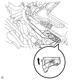
  1. Check that the service plug grip is not installed.

    NOTICE:
    After removing the service plug grip, do not turn the power switch on (READY), unless instructed by the repair manual because this may cause a malfunction.

NOTICE:
Before disconnecting the connector, confirm that it is properly connected by checking that the locking claws are engaged and that the connector does not pull out.

  1. Check the connection of the low voltage connector of the inverter with converter assembly.

    OK:
    The connector is connected securely and there are no contact problems.

    HINT:
    When connecting the connector, insert it with the locking lever in the raised position. Rotate the lever downward and make sure that the connector is pulled into its socket. When the locking lever is in its fully closed position, a click will be heard as its locking claws engage. After the click is heard, pull up on the connector to confirm that it is properly connected.


NG
CONNECT SECURELY
OK


3.CHECK QUANTITY OF HV COOLANT
  1. Check the coolant level in the inverter reserve tank.

  1. Check for coolant leaks.
    Result 
    Result
    Proceed to
    No leaks are found and coolant level in the inverter reserve tank assembly is above the low line.
    A
    No leaks are found and coolant level in the inverter reserve tank assembly is below the low line.
    B
    Coolant leaks are evident.
    C

    HINT:
    After repairing the coolant leaks and adding coolant, perform the "Activate the Water Pump" Active Test (HV Active Test item) and the "Control the Electric Cooling Fan" Active Test (Engine Active Test item) and make sure that there are no malfunctions.


B
ADD HV COOLANT

C
INSPECT FOR COOLANT LEAK AND ADD COOLANT
A


4.CHECK COOLANT HOSE
  1. Check if the hoses of the cooling system are kinked or clogged.


NG
CORRECT THE PROBLEM
OK


5.PERFORM ACTIVE TEST USING INTELLIGENT TESTER (CONTROL THE ELECTRIC COOLING FAN)
  1. Connect the intelligent tester to the DLC3.

  1. Turn the power switch on (IG).

  1. Enter the following menus: Powertrain / Hybrid Control / Trouble Codes.

  1. Clear DTCs and freeze frame data.

  1. Enter the following menus: Powertrain / Engine and ECT / Active Test / Control the Electric Cooling Fan.

  1. Perform the "Control the Electric Cooling Fan" Active Test.

    OK:
    The cooling fan rotates.

  1. Turn the power switch off.


NG
CHECK COOLING FAN SYSTEM (Click here)
OK


6.CHECK HV COOLANT (CHECK FOR CONDITIONS THAT MAY HAVE CAUSED FREEZING)
  1. Connect the intelligent tester to the DLC3.

  1. Turn the power switch on (IG).

  1. Read the freeze frame data Ambient Temperature using the intelligent tester.

  1. Check if the freeze frame data Ambient Temperature is below freezing.

    Result:
    Result
    Proceed to
    Ambient Temperature value is below freezing temperature of the HV coolant
    A
    Ambient Temperature value is above freezing temperature of the HV coolant
    B

    HINT:
    1. HV coolant (SLLC) with a 30% concentration freezes at -15 °C (5°F) and HV coolant (SLLC) with a 50% concentration freezes at -35°C (-31°F).
    2. If the HV coolant freezes in the HV radiator or inverter water pump assembly, the coolant temperature in the inverter with converter assembly rises because the HV coolant cannot circulate. As a result, a DTC may be set.
    3. A DTC is set when the water pump impeller cannot rotate due to freezing of the HV coolant.
    4. If a DTC is set due to freezing of HV coolant, the problem cannot be reproduced. Judge whether freezing of HV coolant occurred according to the freeze point of the HV coolant, HV coolant change history and ambient temperature when the DTC was set.

  1. Turn the power switch off.


B
REPLACE INVERTER WITH CONVERTER ASSEMBLY (Click here)
A


7.REPLACE HV COOLANT
  1. Replace the HV coolant with coolant having an appropriate concentration (appropriate freeze point) for the vehicle usage conditions (Click here).


NEXT

COMPLETED