DTC C1231/31 Steering Angle Sensor Circuit Malfunction |
| DTC Code | INF Code | DTC Detection Condition | Trouble Area |
| C1231/31 | 701 | While steering angle sensor communication is enabled, a malfunction signal output is received during the sensor self-check (sensor malfunction). | Steering angle sensor internal malfunction |
| ↑ | 702 | While steering angle sensor communication is enabled, a malfunction signal output is received during the sensor self-check (internal malfunction). | ↑ |
| ↑ | 703 | While steering angle sensor communication is enabled, a malfunction signal output is received during the sensor self-check (+B malfunction). | ↑ |
| 1.CHECK DTC |
Clear the DTCs (Click here).
Turn the power switch off.
Turn the power switch on (IG) again and check that no CAN communication system DTC is output (Click here).
Drive the vehicle and turn the steering wheel to the right and left at the speed of 35 km/h (22 mph) and check that no speed sensor and/or yaw rate and acceleration sensor DTCs are output (Click here).
| Result | Proceed to |
| DTC (C1231/31) is output | A |
| CAN communication system DTC is output | B |
| Speed sensor and/or yaw rate and acceleration sensor DTC is output | C |
| DTC (C1231/31) is not output | D |
|
| ||||
|
| ||||
|
| ||||
| A | |
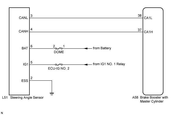
| 2.INSPECT STEERING ANGLE SENSOR (POWER SOURCE TERMINAL) |
 |
Turn the power switch off.
Remove the steering wheel and the column cover.
Make sure that there is no looseness at the locking part and the connecting part of the connector.
Disconnect the steering angle sensor connector.
Measure the voltage according to the value(s) in the table below.
| Tester Connection | Condition | Specified Condition |
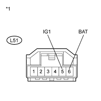
| L51-5 (IG1) - Body ground | Power switch on (IG) | 11 to 14 V |
| L51-6 (BAT) - Body ground | Always | 11 to 14 V |
| *1 | Front view of wire harness connector (to Steering Angle Sensor) |
|
| ||||
| OK | |
| 3.INSPECT STEERING ANGLE SENSOR (GROUND TERMINAL) |
 |
Turn the power switch off.
Measure the resistance according to the value(s) in the table below.
| Tester Connection | Condition | Specified Condition |
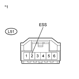
| L51-2 (ESS) - Body ground | Always | Below 1 Ω |
| *1 | Front view of wire harness connector (to Steering Angle Sensor) |
|
| ||||
| OK | ||
| ||
