DTC P3107-215 Airbag ECU Communication Circuit Malfunction |
| DTC No. | INF Code | DTC Detection Condition | Trouble Area |
| P3107 | 215 | Abnormal communication signal |
|
| 1.CHECK DTC OUTPUT (AIRBAG) |
Connect the intelligent tester to the DLC3.
Turn the power switch on (IG).
Enter the following menus: Body Electrical / SRS Airbag / Trouble Codes.
Check if DTCs are output.
| Result | Proceed to |
| Airbag system DTCs are not output. | A |
| Airbag system DTCs are output. | B |
Turn the power switch off.
|
| ||||
| A | |
| 2.CLEAR DTC |
Connect the intelligent tester to the DLC3.
Turn the power switch on (IG).
Enter the following menus: Powertrain / Hybrid Control / Trouble Codes.
Clear DTCs and freeze frame data.
| NEXT | |
| 3.CHECK DTC OUTPUT (HV) |
Connect the intelligent tester to the DLC3.
Turn the power switch on (IG).
Enter the following menus: Powertrain / Hybrid Control / Trouble Codes.
Check if DTCs are output.
| Result | Proceed to |
| DTC P3107-215 is not output. | A |
| DTC P3107-215 is output again. | B |
Turn the power switch off.
|
| ||||
| A | |
| 4.CHECK FOR INTERMITTENT PROBLEMS |
Check for intermittent problems (Click here).
|
| ||||
| OK | ||
| ||
| 5.CHECK AIRBAG SENSOR ASSEMBLY (CHECK WAVEFORM) |
Turn the power switch on (READY).
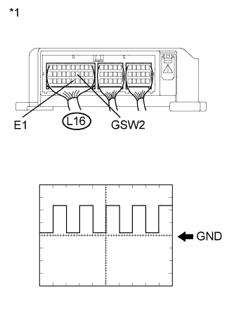 |
Connect an oscilloscope between the airbag sensor assembly terminals specified in the table below, and measure the waveform.
| Item | Contents |
| Terminal | L16-14 (GSW2) - L16-25 (E1) |
| Equipment Setting | 5V/DIV, 500ms/DIV |
| Condition | Power switch on (READY) |
| Result | Proceed to |
| The waveform appears as shown in the illustration. | A |
| The waveform differs from the one shown in the illustration. | B |
| *1 | Component with harness connected (Airbag Sensor Assembly) |
Turn the power switch off.
|
| ||||
| A | ||
| ||
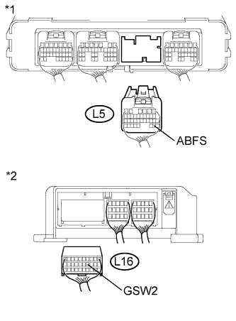
| 6.CHECK CONNECTOR CONNECTION CONDITION (POWER MANAGEMENT CONTROL ECU CONNECTOR) |
Check the connections of the power management control ECU connectors.
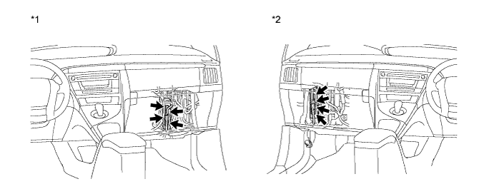
| *1 | for LHD | *2 | for RHD |
|
| ||||
| OK | |
| 7.CHECK CONNECTOR CONNECTION CONDITION (AIRBAG SENSOR ASSEMBLY CONNECTOR) |
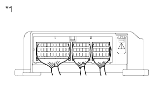 |
Check the connections of the airbag sensor assembly connectors.
| *1 | Component with harness connected (Airbag Sensor Assembly) |
|
| ||||
| OK | |
| 8.CHECK HARNESS AND CONNECTOR (+B SHORT) |
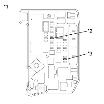 |
Remove the IGCT NO. 2 fuse and AM2 fuse from the engine room junction block assembly.
| *1 | Engine Room Junction Block Assembly |
| *2 | AM2 Fuse |
| *3 | IGCT NO. 2 Fuse |
Disconnect connector L16 from the airbag sensor assembly.
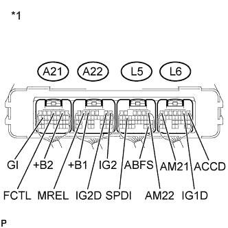 |
Measure the resistance according to the value(s) in the table below.
| Tester Connection | Switch Condition | Specified Condition |
| L5-29 (ABFS) - A21-2 (+B2) | Power switch off | 10 kΩ or higher |
| L5-29 (ABFS) - A22-5 (+B1) | Power switch off | 10 kΩ or higher |
| L5-29 (ABFS) - L5-1 (AM22) | Power switch off | 10 kΩ or higher |
| L5-29 (ABFS) - L6-7 (AM21) | Power switch off | 10 kΩ or higher |
| L5-29 (ABFS) - A22-6 (MREL) | Power switch off | 10 kΩ or higher |
| L5-29 (ABFS) - A22-1 (IG2) | Power switch off | 10 kΩ or higher |
| L5-29 (ABFS) - L6-1 (ACCD) | Power switch off | 10 kΩ or higher |
| L5-29 (ABFS) - L6-2 (IG1D) | Power switch off | 10 kΩ or higher |
| L5-29 (ABFS) - A22-2 (IG2D) | Power switch off | 10 kΩ or higher |
| L5-29 (ABFS) - L5-14 (SPDI) | Power switch off | 10 kΩ or higher |
| L5-29 (ABFS) - A21-16 (GI) | Power switch off | 10 kΩ or higher |
| L5-29 (ABFS) - A21-4 (FCTL) | Power switch off | 10 kΩ or higher |
| *1 | Component with harness connected (Power Management Control ECU) |
Connect the airbag sensor assembly connector.
Install the IGCT NO. 2 fuse and AM2 fuse.
|
| ||||
| OK | |
| 9.CHECK HARNESS AND CONNECTOR (POWER MANAGEMENT CONTROL ECU - AIRBAG SENSOR ASSEMBLY) |
Disconnect connector L5 from the power management control ECU.
Disconnect connector L16 from the airbag sensor assembly.
 |
Measure the resistance according to the value(s) in the table below.
| Tester Connection | Switch Condition | Specified Condition |
| L5-29 (ABFS) - L16-14 (GSW2) | Power switch off | Below 1 Ω |
| Tester Connection | Switch Condition | Specified Condition |
| L5-29 (ABFS) or L16-14 (GSW2) - Body ground and other terminals | Power switch off | 10 kΩ or higher |
| *1 | Rear view of wire harness connector (to Power Management Control ECU) |
| *2 | Rear view of wire harness connector (to Airbag Sensor Assembly) |
Connect the airbag sensor assembly connector.
Connect the power management control ECU connector.
|
| ||||
| OK | ||
| ||
| 10.CHECK HARNESS AND CONNECTOR (SHORT TO POWER SUPPLY WIRES) |
|
Remove the IGCT NO. 2 fuse and AM2 fuse from the engine room junction block assembly.
| *1 | Engine Room Junction Block Assembly |
| *2 | AM2 Fuse |
| *3 | IGCT NO. 2 Fuse |
Disconnect connector L16 from the airbag sensor assembly.
Disconnect all the connectors from the power management control ECU.
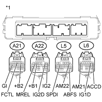 |
Measure the resistance according to the value(s) in the table below.
| Tester Connection | Switch Condition | Specified Condition |
| L5-29 (ABFS) - A21-2 (+B2) | Power switch off | 10 kΩ or higher |
| L5-29 (ABFS) - A22-5 (+B1) | Power switch off | 10 kΩ or higher |
| L5-29 (ABFS) - L5-1 (AM22) | Power switch off | 10 kΩ or higher |
| L5-29 (ABFS) - L6-7 (AM21) | Power switch off | 10 kΩ or higher |
| L5-29 (ABFS) - A22-6 (MREL) | Power switch off | 10 kΩ or higher |
| L5-29 (ABFS) - A22-1 (IG2) | Power switch off | 10 kΩ or higher |
| L5-29 (ABFS) - L6-1 (ACCD) | Power switch off | 10 kΩ or higher |
| L5-29 (ABFS) - L6-2 (IG1D) | Power switch off | 10 kΩ or higher |
| L5-29 (ABFS) - A22-2 (IG2D) | Power switch off | 10 kΩ or higher |
| L5-29 (ABFS) - L5-14 (SPDI) | Power switch off | 10 kΩ or higher |
| L5-29 (ABFS) - A21-16 (GI) | Power switch off | 10 kΩ or higher |
| L5-29 (ABFS) - A21-4 (FCTL) | Power switch off | 10 kΩ or higher |
| *1 | Rear view of wire harness connector (to Power Management Control ECU) |
Connect the power management control ECU connectors.
Connect the airbag sensor assembly connector.
Install the IGCT NO. 2 fuse and AM2 fuse.
|
| ||||
| OK | ||
| ||
