DTC B27A1 Open in Driver Side Electrical Antenna Circuit |
| DTC No. | DTC Detection Condition | Trouble Area |
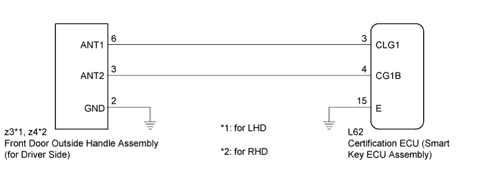
| B27A1 | Open circuit detected between the certification ECU (smart key ECU assembly) and front door outside handle assembly (for driver side) terminals (between CLG1 and ANT1, or CG1B and ANT2). |
|
| 1.CHECK CONNECTOR (CONNECTOR CONNECTION CONDITION) |
Turn the power switch off.
Check that the connectors are properly connected to the certification ECU (smart key ECU assembly) and the front door outside handle assembly (for driver side).
|
| ||||
| OK | |
| 2.CHECK HARNESS AND CONNECTOR (CERTIFICATION ECU - FRONT DOOR OUTSIDE HANDLE) |
Disconnect the certification ECU (smart key ECU assembly) connector.
 |
Disconnect the front door outside handle assembly (for driver side) connector.
Measure the resistance according to the value(s) in the table below.
| Tester Connection | Condition | Specified Condition |
| L62-3 (CLG1) - z3-6 (ANT1) | Always | Below 1 Ω |
| L62-4 (CG1B) - z3-3 (ANT2) | Always | Below 1 Ω |
| L62-3 (CLG1) - Body ground | Always | 10 kΩ or higher |
| L62-4 (CG1B) - Body ground | Always | 10 kΩ or higher |
| z3-6 (ANT1) - Body ground | Always | 10 kΩ or higher |
| z3-3 (ANT2) - Body ground | Always | 10 kΩ or higher |
| Tester Connection | Condition | Specified Condition |
| L62-3 (CLG1) - z4-6 (ANT1) | Always | Below 1 Ω |
| L62-4 (CG1B) - z4-3 (ANT2) | Always | Below 1 Ω |
| L62-3 (CLG1) - Body ground | Always | 10 kΩ or higher |
| L62-4 (CG1B) - Body ground | Always | 10 kΩ or higher |
| z4-6 (ANT1) - Body ground | Always | 10 kΩ or higher |
| z4-3 (ANT2) - Body ground | Always | 10 kΩ or higher |
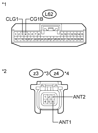
| *1 | Front view of wire harness connector (to Certification ECU (Smart Key ECU Assembly)) |
| *2 | Front view of wire harness connector (to Front Door Outside Handle Assembly (for Driver Side)) |
| *3 | for LHD |
| *4 | for RHD |
|
| ||||
| OK | |
| 3.CHECK HARNESS AND CONNECTOR (FRONT DOOR OUTSIDE HANDLE - BODY GROUND) |
 |
Measure the resistance according to the value(s) in the table below.
| Tester Connection | Condition | Specified Condition |
| z3-2 (GND) - Body ground | Always | Below 1 Ω |
| Tester Connection | Condition | Specified Condition |
| z4-2 (GND) - Body ground | Always | Below 1 Ω |
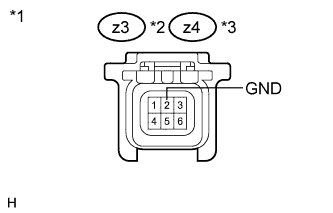
| *1 | Front view of wire harness connector (to Front Door Outside Handle Assembly (for Driver Side)) |
| *2 | for LHD |
| *3 | for RHD |
|
| ||||
| OK | |
| 4.INSPECT CERTIFICATION ECU (SMART KEY ECU ASSEMBLY) (INDOOR ELECTRICAL KEY OSCILLATOR SIGNAL OUTPUT) |
 |
Reconnect the certification ECU (smart key ECU assembly) connector.
Measure the resistance and check for pulses according to the value(s) in the table below.
| Tester Connection | Condition | Specified Condition |
| L62-15 (E) - Body ground | Always | Below 1 Ω |
| Tester Connection | Condition | Specified Condition |
| L62-3 (CLG1) - L62-15 (E) |
| No pulse generation |
| L62-3 (CLG1) - L62-15 (E) |
| Pulse generation |
| L62-4 (CG1B) - L62-15 (E) |
| No pulse generation |
| L62-4 (CG1B) - L62-15 (E) |
| Pulse generation |
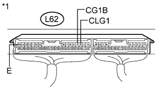
| *1 | Component with harness connected (Certification ECU (Smart Key ECU Assembly)) |
|
| ||||
| OK | |
| 5.REPLACE FRONT DOOR OUTSIDE HANDLE ASSEMBLY (for Driver Side) |
Replace the front door outside handle assembly (for driver side) (Click here).
| NEXT | |
| 6.CHECK DTC OUTPUT |
Clear the DTCs (Click here).
Recheck for DTCs.
|
| ||||
| OK | ||
| ||
