REAR AXLE BEAM > INSTALLATION |
| 1. INSTALL REAR AXLE CARRIER BUSHING LH |
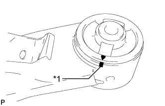 |
Align the arrow mark on a new rear axle carrier bushing LH with the matchmark on the rear axle beam assembly and temporarily install the rear axle carrier bushing LH to the rear axle beam assembly. (If the rear axle beam assembly is reused.)
| *1 | Matchmark |
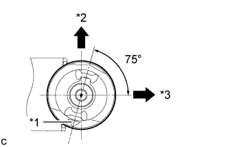 |
Temporarily install the new rear axle carrier bushing LH as shown in the illustration.
| *1 | Mark |
| *2 | Upper Side of the Vehicle |
| *3 | Front of the Vehicle |
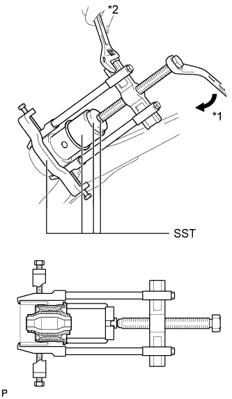 |
Using SST, install the rear axle carrier bushing LH to the rear axle beam assembly.
| *1 | Turn |
| *2 | Hold |
| 2. INSTALL REAR AXLE CARRIER BUSHING RH |
| 3. TEMPORARILY TIGHTEN REAR AXLE BEAM ASSEMBLY |
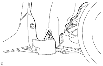
Slowly jack up the rear axle beam assembly with a jack using 2 wooden blocks and 2 attachments or equivalent tools and temporarily install the rear axle beam assembly to the body with the 2 bolts (B).
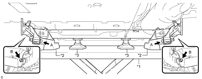
| *1 | Jack | *3 | Attachment |
| *2 | Wooden Block | - | - |
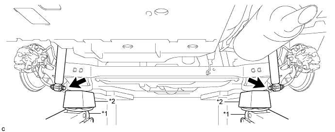
Temporarily tighten the rear axle beam assembly to the rear shock absorber assemblies LH and RH with the 2 bolts (A) and 2 nuts.
| 4. INSTALL REAR UPPER COIL SPRING INSULATOR LH |
 |
Install the rear upper coil spring insulator LH to the rear coil spring LH.
| *1 | 10 mm or less |
| 5. INSTALL REAR UPPER COIL SPRING INSULATOR RH |
| 6. INSTALL REAR LOWER COIL SPRING INSULATOR LH |
| 7. INSTALL REAR LOWER COIL SPRING INSULATOR RH |
| 8. INSTALL REAR COIL SPRING LH |
Support the spring seat of the rear axle beam assembly using 2 jacks and 2 wooden blocks.
| *1 | Jack | *2 | Wooden Block |
Remove the 2 bolts while holding the 2 nuts and separate the rear axle beam assembly from the rear shock absorber assemblies LH and RH.
Slowly lower the rear axle beam assembly using 2 jacks and 2 wooden blocks.
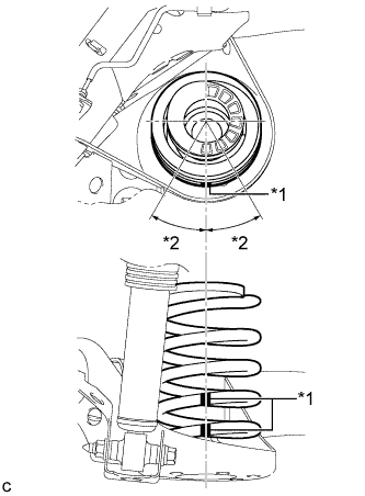 |
Set the rear coil spring LH to the rear axle beam assembly.
| *1 | Identification Mark |
| *2 | 30° or less |
Slowly jack up the rear axle beam assembly using 2 jacks and 2 wooden blocks and temporarily install the rear axle beam assembly and rear coil spring LH with the 2 bolts and 2 nuts.
| *1 | Jack | *2 | Wooden Block |
| 9. INSTALL REAR COIL SPRING RH |
| 10. INSTALL REAR HEIGHT CONTROL SENSOR SUB-ASSEMBLY RH (w/ Height Control Sensor) |
 |
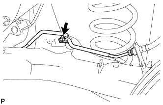
Install the rear height control sensor sub-assembly RH to the rear axle beam assembly with the bolt.
| 11. INSTALL REAR AXLE HUB AND BEARING ASSEMBLY LH |
 |
Install the rear axle hub and bearing assembly and rear disc brake dust cover to the rear axle beam assembly with the 4 bolts.
| 12. INSTALL REAR AXLE HUB AND BEARING ASSEMBLY RH |
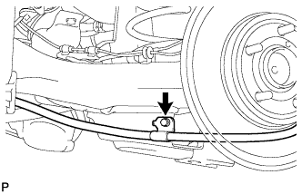
| 13. INSTALL REAR NO. 4 BRAKE TUBE |
 |
Install the rear No. 4 brake tube to the rear axle beam assembly with the nut.
| 14. INSTALL REAR NO. 3 BRAKE TUBE |
| 15. CONNECT REAR BRAKE TUBE FLEXIBLE HOSE |
for LH Side
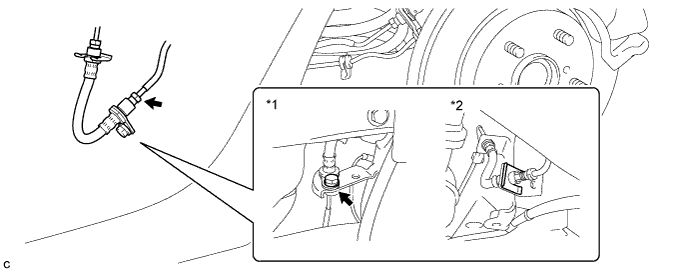
| *1 | LH Side | *2 | RH Side |
Install the rear brake tube flexible hose with the bolt.
for RH Side
Install the rear brake tube flexible hose with a new clip.
Using a union nut wrench, connect the 2 brake lines to the rear brake tube flexible hose.
| 16. INSTALL REAR DISC (for LH Side) |
 |
Align the matchmarks of the disc and axle hub, and install the disc.
| *1 | Matchmark |
| 17. INSTALL REAR DISC (for RH Side) |
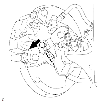
| 18. INSTALL REAR DISC BRAKE CALIPER ASSEMBLY LH |
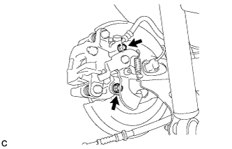 |
Install the rear disc brake caliper assembly LH with rear flexible hose LH with the 2 bolts.
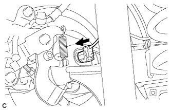
 |
Connect the rear flexible hose LH to the rear axle beam assembly with a new clip.
 |
Using a union nut wrench, connect the brake line to the rear flexible hose LH while holding the rear flexible hose LH with a wrench.
| 19. INSTALL REAR DISC BRAKE CALIPER ASSEMBLY RH |
| 20. INSTALL NO. 3 PARKING BRAKE CABLE ASSEMBLY |
 |
Install the No. 3 parking brake cable assembly to the rear axle beam assembly with the bolt.
| 21. INSTALL NO. 2 PARKING BRAKE CABLE ASSEMBLY |
| 22. CONNECT NO. 3 PARKING BRAKE CABLE ASSEMBLY |
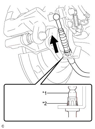 |
Install the No. 3 parking brake cable assembly to the rear disc brake cylinder assembly.
| *1 | No. 3 Parking Brake Cable Assembly |
| *2 | Clip |
 |
Connect the No. 3 parking brake cable assembly to the rear disc brake cylinder assembly.
| 23. CONNECT NO. 2 PARKING BRAKE CABLE ASSEMBLY |
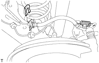
| 24. INSTALL REAR SPEED SENSOR WIRE (for LH Side) |
 |
Install the rear speed sensor wire to the rear axle beam assembly with the nut and 2 clamps.
| 25. INSTALL REAR SPEED SENSOR WIRE (for RH Side) |
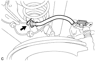
| 26. CONNECT REAR SPEED SENSOR WIRE (for LH Side) |
 |
Connect the rear speed sensor wire connector to the rear speed sensor.
| 27. CONNECT REAR SPEED SENSOR WIRE (for RH Side) |
| 28. INSTALL REAR SUSPENSION BRACE SUB-ASSEMBLY |
Install the rear suspension brace sub-assembly with the 4 bolts and clip.

| 29. INSTALL REAR FLOOR SIDE MEMBER COVER LH |
 |
Install the rear floor side member cover LH with the nut and 2 bolts.
| 30. INSTALL REAR FLOOR SIDE MEMBER COVER RH |
 |
Engage the clip to temporarily install the rear floor side member cover RH.
Install the rear floor side member cover RH with the 3 bolts.
| 31. ADJUST PARKING BRAKE |
| 32. INSTALL LOWER INSTRUMENT PANEL FINISH PANEL ASSEMBLY (for LHD) |
Connect each connector.
Engage the clamp.
Engage the 2 guides and claw to connect the hood lock control cable.
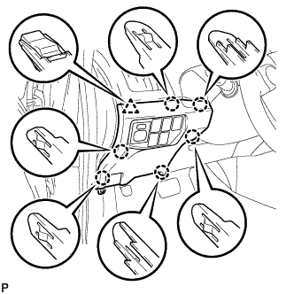 |
Engage the 6 claws and clip.
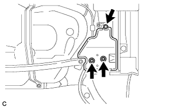
Install the lower instrument panel finish panel assembly with the screw <C>.
| 33. INSTALL COWL SIDE TRIM SUB-ASSEMBLY LH (for LHD) |
 |
Engage the 2 clips.
Install the cowl side trim board LH with the clip.
| 34. INSTALL FRONT DOOR SCUFF PLATE LH (for LHD) |
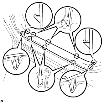 |
Engage the 10 claws to install the front door scuff plate LH.
| 35. INSTALL NO. 1 INSTRUMENT PANEL UNDER COVER SUB-ASSEMBLY (for RHD) |
Connect each connector.
Engage the guide and 2 claws.
Install the No. 1 instrument panel under cover sub-assembly with the screw <D>.
| 36. FILL RESERVOIR WITH BRAKE FLUID |
| 37. CONNECT CABLE TO NEGATIVE BATTERY TERMINAL |
| 38. INSTALL REAR NO. 3 FLOOR BOARD |
 |
Engage the 2 guides to install the rear No. 3 floor board.
| 39. INSTALL REAR DECK FLOOR BOX |
Install the rear deck floor box.
| 40. INSTALL REAR NO. 2 FLOOR BOARD |
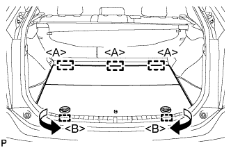 |
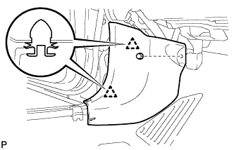
Engage the 3 guides <A>.
Engage the 2 guides <B> and install the rear No. 2 floor board as shown in the illustration.
| 41. BLEED BRAKE LINE |
Remove the center cowl top ventilator cover.
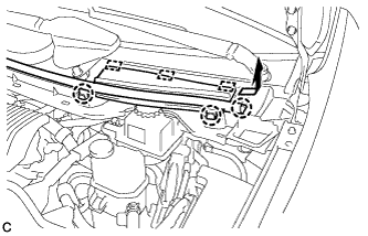 |
Slide the hood to cowl top seal and disengage the claw.
Disengage the 2 claws and 3 guides, and remove the center cowl top ventilator cover.
Bleed brake line.
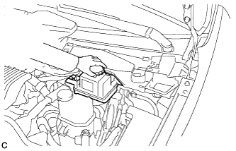 |
Remove the brake master cylinder reservoir filler cap assembly.
Add brake fluid into the reservoir between MAX and MIN level on the brake fluid reservoir.
Connect the intelligent tester to the DLC3 and turn the power switch on (IG).
Turn the intelligent tester on and enter the following menus: Chassis / ABS/VSC/TRC / Air Bleeding.
Select the "Usual air bleeding" on the intelligent tester display, and bleed air from the brake fluid following the instructions on the intelligent tester.
After air bleeding, tighten each bleeder plug.
Clear the DTCs (Click here).
Turn the intelligent tester off and turn the power switch off.
Inspect for brake fluid leaks.
Install the brake master cylinder reservoir filler cap.
Install the center cowl top ventilator cover.
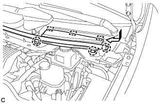 |
Engage the 2 claws and 3 guides to install the center cowl top ventilator cover.
Slide the hood to cowl top seal to engage the claw.
| 42. INSTALL REAR WHEELS |
| 43. STABILIZE SUSPENSION |
Lower the vehicle.
Bounce the vehicle up and down several times to stabilize the suspension.
| 44. FULLY TIGHTEN REAR AXLE BEAM ASSEMBLY |
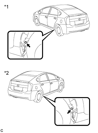 |
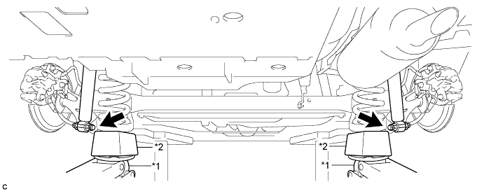
Fully tighten the 2 bolts.
| *1 | LH Side |
| *2 | RH Side |
 |
Fully tighten the 2 bolts.
| *1 | LH Side |
| *2 | RH Side |
| 45. INSTALL REAR WHEEL HOUSE LINER LH |
 |
Install the rear wheel house liner LH with the clip.
| 46. INSTALL REAR WHEEL HOUSE LINER RH |
| 47. INSPECT REAR WHEEL ALIGNMENT |
| 48. PLACE FRONT WHEELS FACING STRAIGHT AHEAD |
| 49. PERFORM YAW RATE AND ACCELERATION SENSOR CALIBRATION |
| 50. CHECK FOR SPEED SENSOR SIGNAL |
| 51. PERFORM INITIALIZATION (w/ Height Control Sensor) |
