DTC P0340 Camshaft Position Sensor Circuit Malfunction |
DTC P0342 Camshaft Position Sensor "A" Circuit Low Input (Bank 1 or Single Sensor) |
DTC P0343 Camshaft Position Sensor "A" Circuit High Input (Bank 1 or Single Sensor) |
| DTC No. | DTC Detection Condition | Trouble Area |
| P0340 | When ether of following conditions is met:
|
|
| P0342 | Output voltage of camshaft position sensor less than 0.3 V for 4 seconds (1 trip detection logic) |
|
| P0343 | Output voltage of 4.7 V for 4 seconds (1 trip detection logic) |
|
| 1.CHECK ANY OTHER DTCS OUTPUT (IN ADDITION TO DTC P0340, P0342 AND P0343) |
Connect the intelligent tester to the DLC3.
Turn the power switch on (IG).
Turn the tester on.
Enter the following menus: Powertrain / Engine and ECT / DTC.
Read the DTCs.
| Result | Proceed to |
| DTC P0340, P0342 or P0343 is output | A |
| DTC P0340, P0342 or P0343 and other DTCs are output | B |
|
| ||||
| A | |
| 2.INSPECT CAMSHAFT POSITION SENSOR (POWER SOURCE) |
 |
Disconnect the camshaft position sensor connector.
Turn the power switch on (IG).
Measure the voltage according to the value(s) in the table below.
| Tester Connection | Switch Condition | Specified Condition |
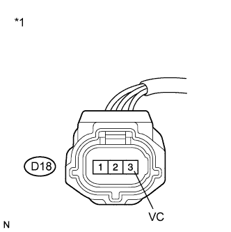
| D18-3 (VC) - Body ground | Power switch on (IG) | 4.5 to 5.0 V |
| *1 | Front view of wire harness connector (to Camshaft Position Sensor) |
Reconnect the camshaft position sensor connector.
|
| ||||
| OK | |
| 3.CHECK HARNESS AND CONNECTOR (CAMSHAFT POSITION SENSOR - ECM) |
Disconnect the camshaft position sensor connector.
Disconnect the ECM connector.
Measure the resistance according to the value(s) in the table below.
| Tester Connection | Condition | Specified Condition |
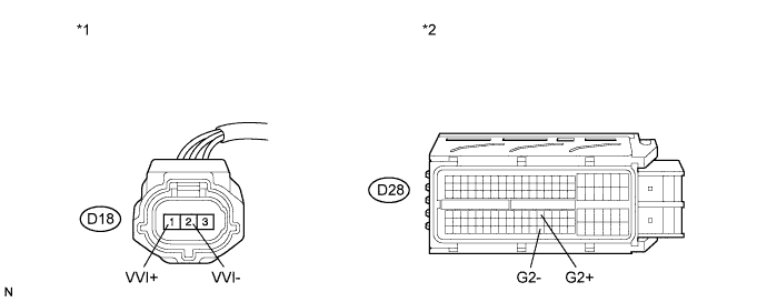
| D18-1 (VVI+) - D28-76 (G2+) | Always | Below 1 Ω |
| D18-2 (VVI-) - D28-122 (G2-) | Always | Below 1 Ω |
| Tester Connection | Condition | Specified Condition |
| D18-1 (VVI+) or D28-76 (G2+) - Body ground | Always | 10 kΩ or higher |
| D18-2 (VVI-) or D28-122 (G2-) - Body ground | Always | 10 kΩ or higher |
| *1 | Front view of wire harness connector (to Camshaft Position Sensor) | *2 | Front view of wire harness connector (to ECM) |
Reconnect the camshaft position sensor connector.
Reconnect the ECM connector.
|
| ||||
| OK | |
| 4.CHECK SENSOR INSTALLATION (CAMSHAFT POSITION SENSOR) |
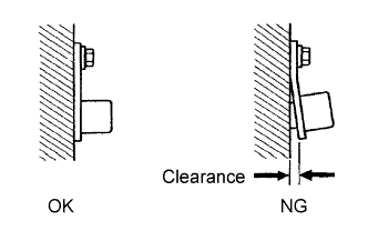 |
Check the camshaft position sensor installation.
|
| ||||
| OK | |
| 5.INSPECT INTAKE CAMSHAFT (TIMING ROTOR) |
Check the timing rotor of the intake camshaft.
|
| ||||
| OK | |
| 6.REPLACE CAMSHAFT POSITION SENSOR |
Replace the camshaft position sensor (Click here).
| NEXT | |
| 7.CHECK WHETHER DTC OUTPUT RECURS (P0340, P0342 OR P0343) |
Connect the intelligent tester to the DLC3.
Turn the power switch on (IG).
Turn the tester on.
Clear the DTCs (Click here).
Put the engine in inspection mode (Click here).
Start the engine and wait for 10 seconds.
Enter the following menus: Powertrain / Engine and ECT / DTC.
Read the DTCs.
| Result | Proceed to |
| DTC P0340, P0342 or P0343 is output | A |
| DTC is not output | B |
|
| ||||
| A | |
| 8.ADJUST VALVE TIMING |
 |
| *1 | Top |
| *2 | Alignment Mark |
| *3 | No. 1 Cylinder at TDC Compression |
| NEXT | |
| 9.CHECK WHETHER DTC OUTPUT RECURS (P0340, P0342 OR P0343) |
Connect the intelligent tester to the DLC3.
Turn the power switch on (IG).
Turn the tester on.
Clear the DTCs (Click here).
Put the engine in inspection mode (Click here).
Start the engine and wait for 10 seconds.
Enter the following menus: Powertrain / Engine and ECT / DTC.
Read the DTCs.
| Result | Proceed to |
| DTC is not output | A |
| DTC P0340, P0342 or P0343 is output | B |
|
| ||||
| A | ||
| ||
| 10.CHECK HARNESS AND CONNECTOR (CAMSHAFT POSITION SENSOR - ECM) |
Disconnect the camshaft position sensor connector.
Disconnect the ECM connector.
Measure the resistance according to the value(s) in the table below.
| Tester Connection | Condition | Specified Condition |
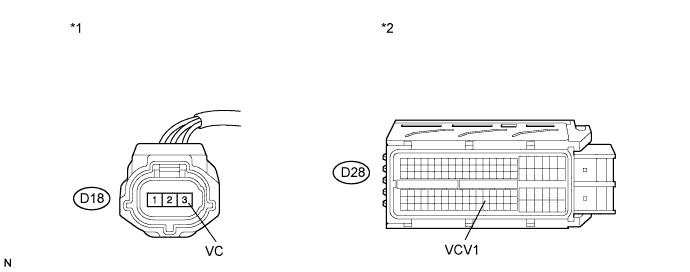
| D18-3 (VC) - D28-99 (VCV1) | Always | Below 1 Ω |
| Tester Connection | Condition | Specified Condition |
| D18-3 (VC) or D28-99 (VCV1) - Body ground | Always | 10 kΩ or higher |
| *1 | Front view of wire harness connector (to Camshaft Position Sensor) | *2 | Front view of wire harness connector (to ECM) |
Reconnect the camshaft position sensor connector.
Reconnect the ECM connector.
|
| ||||
| OK | ||
| ||
