DTC P0102 Mass or Volume Air Flow Circuit Low Input |
DTC P0103 Mass or Volume Air Flow Circuit High Input |
| DTC No. | DTC Detection Condition | Trouble Area |
| P0102 | Mass air flow meter voltage less than 0.2 V for 3 seconds (1 trip detection logic) |
|
| P0103 | Mass air flow meter voltage more than 4.9 V for 3 seconds (1 trip detection logic) |
|
| Mass Air Flow Rate (gm/sec) | Malfunction |
| Approximately 0.0 |
|
| 271.0 or more | Open in E2G circuit |
| 1.READ DTC OUTPUT |
Connect the intelligent tester to the DLC3.
Turn the power switch on (IG).
Turn the tester on.
Enter the following menus: Powertrain / Engine and ECT / DTC.
Read the DTCs.
| Result | Proceed to |
| DTC P0102 is output | A |
| DTC P0103 is output | B |
|
| ||||
| A | |
| 2.INSPECT MASS AIR FLOW METER SUB-ASSEMBLY (POWER SOURCE VOLTAGE) |
 |
Disconnect the mass air flow meter sub-assembly connector.
Turn the power switch on (IG).
Measure the voltage according to the value(s) in the table below.
| Tester Connection | Switch Condition | Specified Condition |
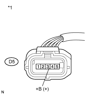
| D5-3 (+B) - Body ground | Power switch on (IG) | 11 to 14 V |
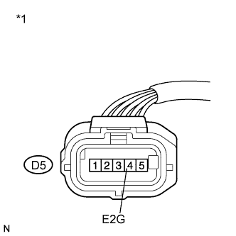
| *1 | Front view of wire harness connector (to Mass Air Flow Meter Sub-assembly) |
Reconnect the mass air flow meter sub-assembly connector.
|
| ||||
| OK | |
| 3.CHECK HARNESS AND CONNECTOR (MASS AIR FLOW METER SUB-ASSEMBLY - ECM) |
Disconnect the mass air flow meter sub-assembly connector.
Disconnect the ECM connector.
Measure the resistance according to the value(s) in the table below.
| Tester Connection | Condition | Specified Condition |
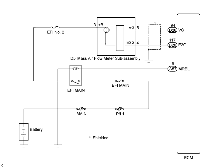
| D5-5 (VG) - D28-94 (VG) | Always | Below 1 Ω |
| D5-4 (E2G) - D28-117 (E2G) |
| Tester Connection | Condition | Specified Condition |
| D5-5 (VG) or D28-94 (VG) - Body ground | Always | 10 kΩ or higher |
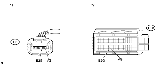
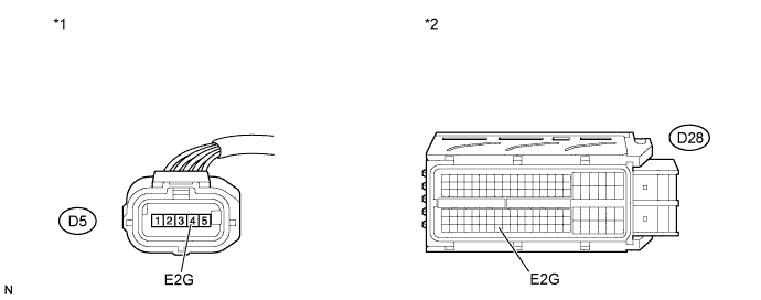
| *1 | Front view of wire harness connector (to Mass Air Flow Meter Sub-assembly) | *2 | Front view of wire harness connector (to ECM) |
Reconnect the mass air flow meter sub-assembly connector.
Reconnect the ECM connector.
|
| ||||
| OK | |
| 4.INSPECT MASS AIR FLOW METER SUB-ASSEMBLY |
 |
Perform On-vehicle inspection (Click here).
Perform Inspection (Click here).
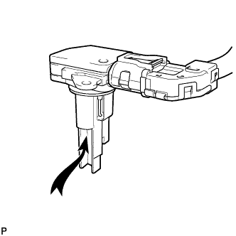
Inspect the function of the mass air flow meter sub-assembly.
Remove the mass air flow meter sub-assembly with the connector connected.
Connect the intelligent tester to the DLC3.
Turn the power switch on (IG).
Turn the tester on.
Enter the following menus: Powertrain / Engine and ECT / Data List / MAF.
Blow air to the mass air flow meter sub-assembly and check that the intake air amount reading changes.
|
| ||||
| OK | ||
| ||
| 5.CHECK HARNESS AND CONNECTOR (SENSOR GROUND) |
 |
Disconnect the mass air flow meter meter sub-assembly connector.
Measure the resistance according to the value(s) in the table below.
| Tester Connection | Condition | Specified Condition |
| D5-4 (E2G) - Body ground | Always | Below 1 Ω |
| *1 | Front view of wire harness connector (to Mass Air Flow Meter Sub-assembly) |
Reconnect the mass air flow meter sub-assembly connector.
|
| ||||
| OK | ||
| ||
| 6.CHECK HARNESS AND CONNECTOR (MASS AIR FLOW METER SUB-ASSEMBLY - ECM) |
Disconnect the mass air flow meter sub-assembly connector.
Disconnect the ECM connector.
Measure the resistance according to the value(s) in the table below.
| Tester Connection | Condition | Specified Condition |
| D5-4 (E2G) - D28-117 (E2G) | Always | Below 1 Ω |
| *1 | Front view of wire harness connector (to Mass Air Flow Meter Sub-assembly) | *2 | Front view of wire harness connector (to ECM) |
Reconnect the mass air flow meter sub-assembly connector.
Reconnect the ECM connector.
|
| ||||
| OK | ||
| ||
