Home

Toyota Workshop

GSIC - Global Service Information Center

DTC    P0560    System Voltage

for Preparation Click here


DESCRIPTION

The battery supplies electricity to the ECM even when the power switch is off. This power allows the ECM to store data such as DTC history, freeze frame data and fuel trim values. If the battery voltage falls below a minimum level, the memory is cleared and the ECM determines that there is a malfunction in the power supply circuit. The next time the engine is started, the ECM illuminates the MIL and sets the DTC.

DTC No.
DTC Detection Condition
Trouble Area
P0560
Open in ECM back up power source circuit
(1 trip detection logic)
  1. Open in back up power source circuit
  2. Battery
  3. Battery terminals
  4. EFI MAIN fuse
  5. ECM

HINT:
If DTC P0560 is set, the ECM does not store other DTCs or the data stored in the ECM may be partly cleared.


WIRING DIAGRAM


A157717E17


INSPECTION PROCEDURE

NOTICE:
Inspect the fuses for circuits related to this system before performing the following inspection procedure.

HINT:
Read freeze frame data using the intelligent tester. The ECM records vehicle and driving condition information as freeze frame data the moment a DTC is stored. When troubleshooting, freeze frame data can be helpful in determining whether the vehicle was running or stopped, whether the engine was warmed up or not, whether the air fuel ratio was lean or rich, as well as other data recorded at the time of a malfunction.

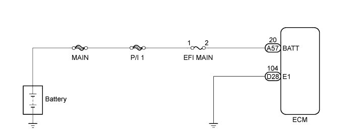
1.CHECK HARNESS AND CONNECTOR (ECM - EFI MAIN FUSE)


  1. Disconnect the negative battery terminal.


    A216516E04

  1. Disconnect the positive battery terminal.

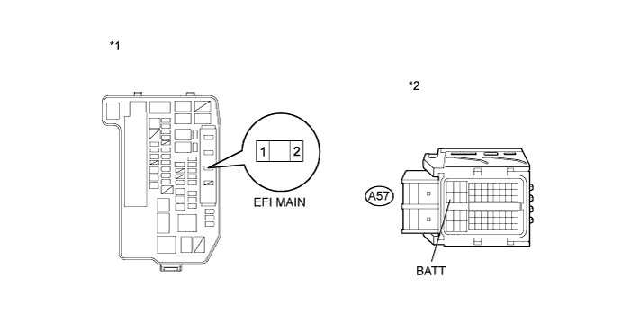
  1. Remove the EFI MAIN fuse from the engine room relay block.

  1. Disconnect the ECM connector.

  1. Measure the resistance according to the value(s) in the table below.

    Standard Resistance (Check for Open):

    Tester Connection
    Condition
    Specified Condition
    EFI MAIN fuse (2) - A57-20 (BATT)
    Always
    Below 1 Ω


    Standard Resistance (Check for Short):

    Tester Connection
    Condition
    Specified Condition
    EFI MAIN fuse (2) or A57-20 (BATT) - Body ground
    Always
    10 kΩ or higher


    Text in Illustration 
    *1
    Engine Room Relay Block
    *2
    Front view of wire harness connector
    (to ECM)

  1. Reinstall the EFI MAIN fuse.

  1. Reconnect the ECM connector.

  1. Reconnect the positive battery terminal.

  1. Reconnect the negative battery terminal.


NG
REPAIR OR REPLACE HARNESS OR CONNECTOR (ECM - EFI MAIN FUSE)
OK


2.INSPECT BATTERY
  1. Check that the battery is not discharged or weak.

    OK:
    Battery is not discharged or weak.


NG
CHARGE OR REPLACE BATTERY
OK


3.CHECK BATTERY TERMINAL
  1. Check that the battery terminals are not loose or corroded.

    OK:
    Battery terminals are not loose or corroded.


NG
REPAIR OR REPLACE BATTERY TERMINAL
OK


4.CHECK WHETHER DTC OUTPUT RECURS
  1. Connect the intelligent tester to the DLC3.

  1. Turn the power switch on (IG).

  1. Turn the tester on.

  1. Clear the DTCs (Click here).

  1. Turn the power switch off and turn the tester off.

  1. Turn the power switch on (IG) and turn the tester on.

  1. Wait 5 seconds or more.

  1. Enter the following menus: Powertrain / Engine and ECT / DTC.

  1. Read the DTCs.

    Result:
    Result
    Proceed to
    DTC P0560 is output
    A
    DTC is not output
    B


B
CHECK FOR INTERMITTENT PROBLEMS (Click here)
A

REPLACE ECM (Click here)